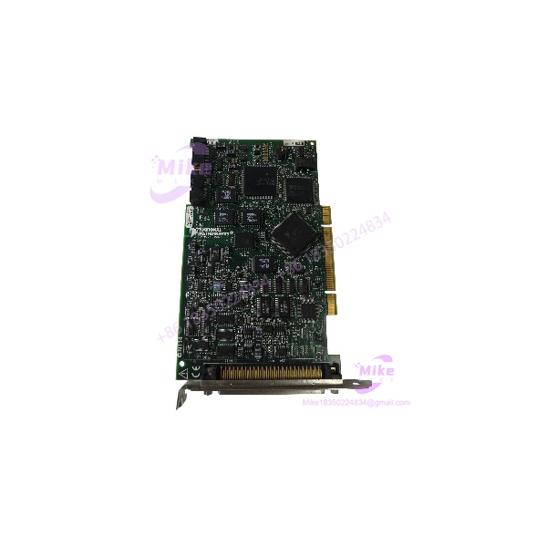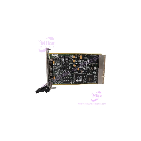
Description
NI PXI-6713 | 1 MS/s 12-Bit Analog Output Module
Dynamic Product Introduction
Sourcing functional legacy DAQ hardware for critical test stands often turns into a race against obsolescence. When precise waveform generation or closed-loop control loops require rapid voltage response, the NI PXI-6713 provides the throughput necessary to keep legacy Automated Test Equipment (ATE) operational without costly software rewrites.
Unlike lower-tier software-timed boards, the PXI-6713 relies on dedicated onboard FIFO buffers and direct DMA channels to deliver simultaneous output updates up to 1 MS/s per channel across all 8 voltage outputs. | This hardware-timed performance makes the PXI-6713 an essential component for hardware-in-the-loop (HIL) simulation, automated calibration rigs, and high-frequency transducer driving.
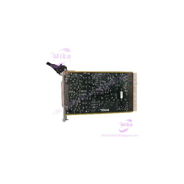
PXI-6713
Key Technical Specifications
- Analog Output Channels: 8 voltage outputs |
- DAC Resolution: 12 bits |
- Maximum Update Rate: 1 MS/s per channel |
- Output Range: ±10 V (Bipolar) |
- FIFO Buffer Size: 2,048 samples
- Digital I/O Lines: 8 TTL lines (software or hardware-timed) |
- Counter/Timers: 2 independent 24-bit, 20 MHz counter/timers |
- Triggering: Analog and Digital triggers via PXI Backplane (PXI Trigger Bus / RTSI) |
- Bus Interface: 32-bit PXI / CompactPCI standard
- Connector Type: 68-pin female SCSI (VHDCI / 68-pin A)
Global Sourcing & Live-Test SOP (Transparency Core)
In field deployments, surplus or refurbished PXI modules require rigorous verification before installation into production test stands.
Inbound Verification & OEM Traceability
- Paperwork Audit: Validation of original serial numbers against NI manufacturing databases to verify production batch integrity.
- Physical Inspection: Comprehensive examination for pin corrosion, damaged backplane connectors, modified PCB traces, or thermal stress on DAC ICs.
Live Rack Simulation & Diagnostics
- Backplane Benchmarking: Placed on an authentic PXI/PXIe hybrid chassis to verify PCI bus recognition, DMA controller handshake, and address space allocation.
- Full-Scale I/O Simulation: High-speed oscilloscope and Fluke multimeter verification of step-response times, output linearity, gain/offset drift, and rail-to-rail voltage stability at ±10 V. |
- Bus Integration Test: Verification of PXI Star Triggering and RTSI line timing synchronization across multi-card setups. |
- 24-Hour Stress Run: Module is operated at full 1 MS/s update rates across all 8 channels continuously inside a thermal chamber to guarantee thermal tolerance. |
Final Shipping Prep
- Firmware & Calibration: Verification of factory EEPROM calibration coefficients.
- ESD Safe Handling: Sealed in anti-static shielding bags with desiccant packs inside reinforced packaging for international freight.
The Field Engineer’s Pitfall Guide
- ❗ Driver Version & OS Architecture Compatibility: Replacing a PXI-6713 in a legacy Windows XP/7 system with modern NI-DAQmx drivers can break application calls. Legacy Traditional NI-DAQ (Legacy) and early NI-DAQmx versions handle FIFO buffer allocations differently. Ensure your driver stack matches the original system build before swapping hardware.
- ❗ Over-Current & Drive Limits: The PXI-6713 can source up to 5 mA per channel (40 mA total across all 8 channels). | Attempting to drive low-impedance inductive loads directly—like heavy relay coils or unbuffered actuators—will drop output voltage rails, trigger short-circuit protection, or burn out output op-amps. Always verify load impedance exceeds 2 kΩ.
- ❗ PXI Backplane Trigger Routing: When replacing an existing module in a multi-chassis setup, forgetting to re-map RTSI / PXI Trigger Bus line assignments in Measurement & Automation Explorer (MAX) will cause signal generation to hang indefinitely while waiting for an unrouted digital trigger. |
Intent-Driven FAQ
Will I lose my custom waveform settings if I swap out a damaged PXI-6713?
No. Waveform generation patterns and timing sequences are stored in your host controller’s RAM or software application (LabVIEW, C++, MATLAB) and streamed to the card’s onboard FIFO via DMA. The card itself holds no volatile application logic once powered down.
Is the PXI-6713 hot-swappable during system operation?
No. Standard PXI cards do not support live hot-swapping unless the chassis explicit supports hot-swap slots. Always power down the PXI chassis completely before removing or inserting the PXI-6713 module to prevent backplane pin arcing and FPGA damage.
Can I run the PXI-6713 in a newer PXI Express (PXIe) chassis?
The PXI-6713 uses a standard 32-bit PXI/CompactPCI connector. It can only be installed in standard PXI slots or hybrid PXIe slots. It will not physically fit or interface with dedicated PXIe-only slots.
What is the difference between the PXI-6711 and PXI-6713?
The primary difference is channel density. The PXI-6711 features 4 analog output channels, whereas the PXI-6713 features 8 analog output channels. | Both offer 12-bit resolution and 1 MS/s per channel update rates.