Description
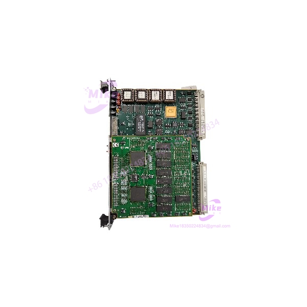
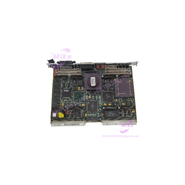
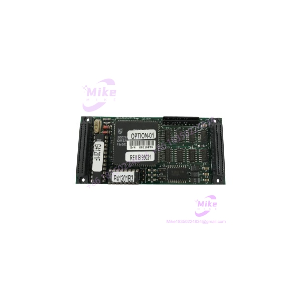
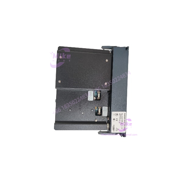
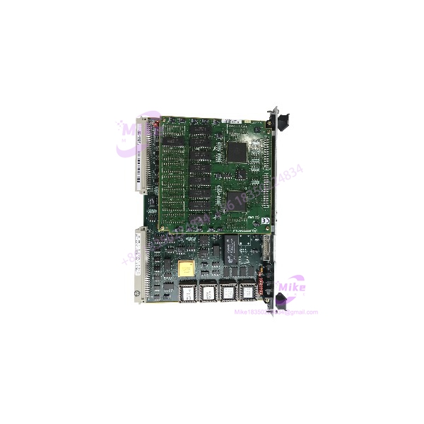
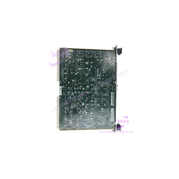
Motorola MVME187-CP109 | MC68040 33MHz VME CPU Board
Dynamic Product Introduction
Plagued by unexplainable backplane bus faults or sporadic kernel panics on legacy process control lines? In older industrial installations running high-reliability VMEbus architectures, a failing CPU board usually brings the entire automation cell down without warning. The MVME187-CP109 single board computer remains a foundational workhorse for legacy process control loops, turbine controls, and embedded real-time systems where stability trumps modern processing overkill. Equipped with the classic 33 MHz Motorola MC68040 processor, this module integrates memory management, floating-point math execution, and local I/O handling on a single double-Eurocard board.
Swapping out a degraded processing node for a fully verified MVME187-CP109 eliminates the unpredictable timing drift and thermal-induced memory errors that plague aging hardware. Rather than undertaking a multi-million-dollar system overhaul that risks weeks of unbudgeted downtime, dropping in a clean, factory-spec MVME187-CP109 restores deterministic real-time processing instantly. It retains exact clock timing, register behaviors, and peripheral address mappings demanded by legacy VxWorks or OS-9 real-time environments.
MVME187-CP109
Key Technical Specifications
- Processor Architecture: Motorola MC68040 32-bit RISC-like CISC Processor
- Clock Frequency: 33 MHz internal logic clock
- Floating Point Unit: Integrated MC68040 hardware FPU
- Bus Architecture: VMEbus IEEE 1014-1987 compliant (A32/D32 master/slave capabilities)
- On-Board Memory: High-density DRAM options with parity protection (configuration-dependent)
- Storage Interfaces: Integrated SCSI-1/SCSI-2 controller interface
- Network / Communications: On-board Ethernet interface (AUI connector), dual RS-232 serial ports
- Timers: Multi-channel programmable timers and watchdog counter
- Form Factor: Standard 6U VMEbus form factor (Double-Eurocard, single-slot width)
- Power Requirements: +5V DC primary system backplane power rail
- Operating Temperature Range: 0°C to +55°C (32°F to 131°F) under forced-air cooling
Global Sourcing & Live-Test SOP (Transparency Core)
Procuring legacy hardware like the MVME187-CP109 requires rigorous verification before installation on an active plant floor.
Inbound Verification
Every incoming MVME187-CP109 undergoes thorough visual inspection. We cross-reference OEM silkscreen markings, PCB revisions, and physical trace integrity under optical magnification. Serial tags are audited against surplus chain records to confirm authentic OEM manufacturing origin and prevent counterfeit or poorly reworked units from entering inventory.
Live Simulation
Modules are inserted into an authentic, powered 6U VMEbus test chassis with calibrated power supplies. The card is initialized under real-world bus arbitration configurations alongside active master and slave I/O boards to test backplane handshake timing.
Diagnostics
Testing begins with a full address and data line pattern test across onboard RAM. We establish an active Ethernet link, test the SCSI host adapter interface via disk read/write loops, and run full-scale serial communications on both RS-232 ports. The system runs a 24-hour full-load thermal burn-in while monitoring voltage drops across the primary 5V rail using calibrated Fluke digital multimeters.
Final Prep
Upon successful pass, onboard jumper settings are documented, battery backup states (where applicable) are verified, and the board is sealed in ESD-shielded anti-static packaging with desiccant packs ready for dispatch.
The Field Engineer’s Pitfall Guide
❗ Jumper and Option Header Mismatches: Before sliding the into the rack, meticulously mirror every onboard jumper block (e.g., system controller configuration, VME bus request levels, RAM map settings, and serial clock sources) from the failed unit. I’ve seen plant technicians burn through two full shifts troubleshooting a “dead” CPU, only to realize the replacement was jumpered as a bus slave instead of the primary system controller.
❗ VMEbus Backplane Pin Damage and Alignment: Inspect the backplane P1 and P2 connectors thoroughly before insertion. The fine pins on older VME backplanes easily bend or fracture if the card is forced into alignment. Inserting an into a bent P1 pin array can short the main +5V rail straight to ground, frying the onboard trace paths immediately upon power-up.
❗ SCSI Bus Termination and Address Conflicts: If your architecture boot-loads or logs data via the integrated SCSI bus, verify that total bus termination rules are strictly preserved. Missing active termination or matching SCSI IDs with external drive units will freeze the bootloader during the initial hardware probe—leaving the system hanging before the OS kernel ever loads.
Intent-Driven FAQ
Will swapping to a replacement corrupt my existing real-time logic or software application?
No, the board executes software at the hardware layer. However, software logic stored in onboard volatile memory will be lost if not backed up. Ensure you transfer existing EPROMs/NVRAM chips or reflash the application image via network/serial boot interfaces during replacement.
Can I hot-swap the while the VME chassis is powered on?
Absolutely not. Standard VMEbus systems do not support live hot-swapping for standard processing cards. Power down the rack entirely before removing or inserting the to prevent backplane arcing and bus corruption.
How do I know if my failure is caused by power delivery issues rather than a dead CPU?
Use a digital multimeter to measure voltage directly at the VME backplane P1 connector while the rack is under load. If the +5V rail sags below +4.75V DC, the onboard processor watchdog will trigger continuous resets, mimicking a dead board.
What is the expected availability and life cycle status for this unit?
The is a mature, OEM-discontinued product. Supply relies exclusively on fully qualified surplus, tested working stock, and reconditioned units sourced through specialized industrial hardware suppliers.
Does the board ship with pre-configured jumper positions?
Units are typically shipped in a default standard factory layout or in the last verified test state. You must inspect and set the jumper headers to match your specific cabinet’s backplane configuration prior to applying power.