Description
Motorola MVME162-031 | VME SBC Ready To Ship Today
Architect’s Product Breakdown
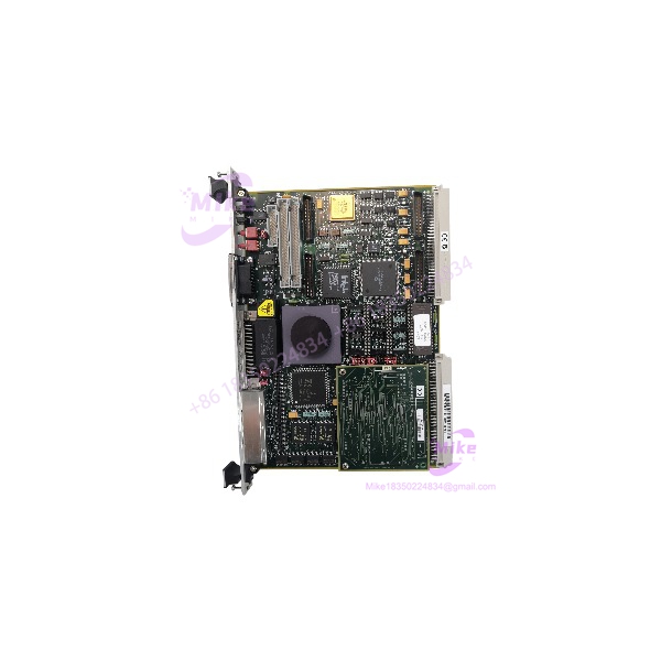
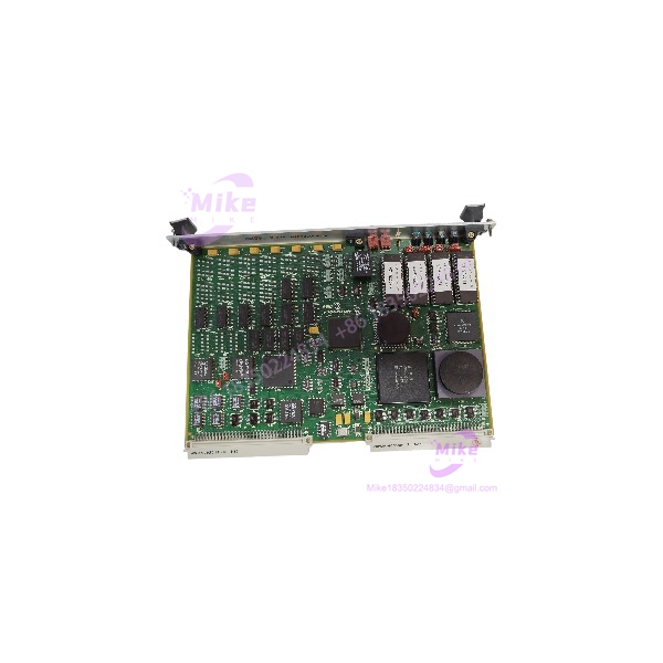
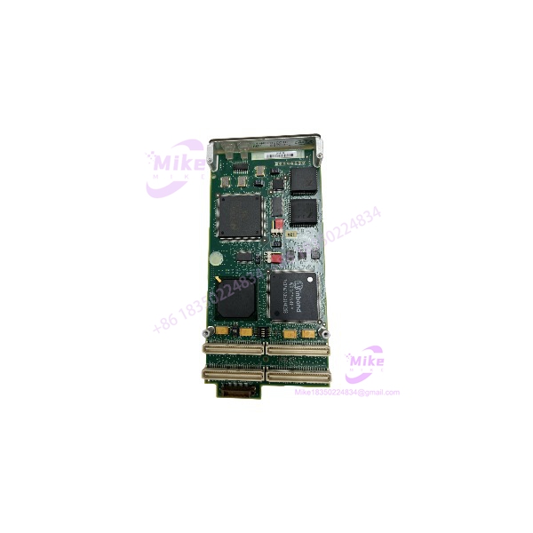
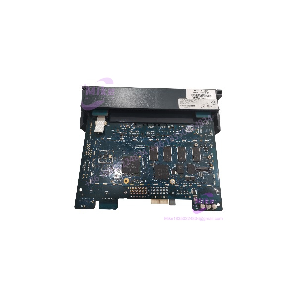
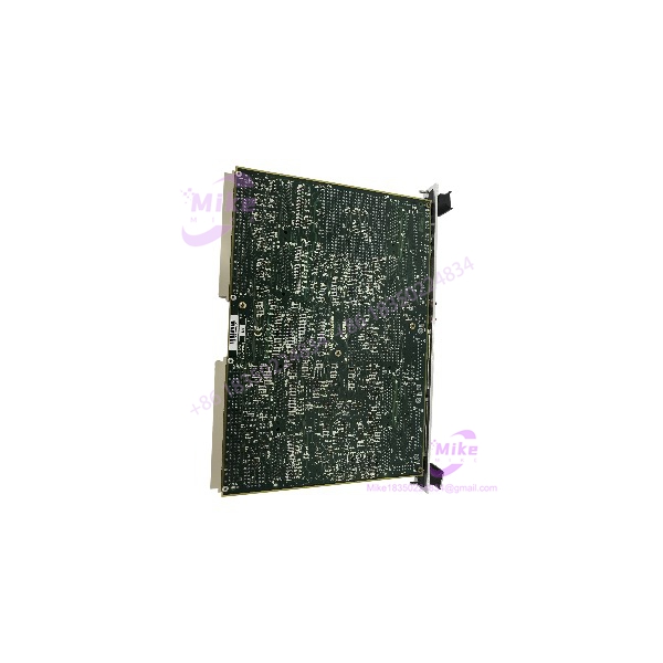
The Motorola MVME162-031 is a high-performance 32-bit single-board computer built for rigorous VMEbus industrial control applications. Powered by a full MC68040 processor featuring an integrated floating-point unit and memory management unit, this module manages local application execution, hardware control, and high-speed communication across the backplane chassis without requiring external coprocessor cards.
Configuring this hardware demands careful attention to onboard jumper settings for base memory mapping, interrupt request levels, and serial/Ethernet port configurations. Because these embedded systems operate in continuous-duty industrial environments, proper thermal management and adherence to backplane power budgets are mandatory to prevent premature component failure.
Deploying the MVME162-031 allows maintenance teams to sustain legacy VME infrastructures efficiently, avoiding the extensive downtime and software rewrite costs associated with total system platform migrations.
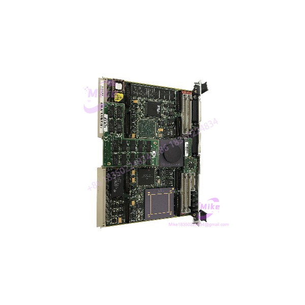
MVME162-031
Key Technical Specifications
| Technical Parameter | Specification Detail |
| Part Number | MVME162-031 |
| Manufacturer | Motorola / VMEbus Platforms |
| Processor Architecture | Motorola MC68040 32-bit Microprocessor (with FPU/MMU) |
| Bus Interface | VMEbus Standard Compliant (System Controller capable) |
| Memory Configuration | Onboard DRAM and flash/ROM sockets for firmware storage |
| Communication Ports | Onboard Ethernet interface and multiple serial communication channels |
| Operating Temperature | 0°C to 55°C (32°F to 131°F) |
| Form Factor | Standard VMEbus single-height circuit card |
Field Engineer’s Pitfall Guide
- WARNING: Electrostatic Discharge Vulnerability. The high-density surface-mount components on this CPU board are highly sensitive to static electricity. Always utilize an ESD-safe grounded wrist strap during handling.
- WARNING: Base Address and Interrupt Conflicts. Replacing a failed board without matching the exact jumper configurations for memory mapping and interrupt levels will cause immediate bus collisions and system faults.
- WARNING: Firmware/Flash Corruption. Interrupted power cycles during flash memory writes or using incorrect programming routines can render the boot sector unreadable.
Field Anecdote: During an emergency service window on a manufacturing line controller, a technician swapped an ailing MVME162-031 with a warehouse spare without verifying the onboard jumper blocks. The replacement card booted up but immediately generated a bus timeout error because the base memory address jumpers were set to factory default rather than the custom offset required by their legacy I/O mapping. Aligning the jumpers cleared the fault instantly.
QA & Testing SOP (Transparency)
- Visual & Origin Inspection: Inspected under optical magnification for PCB trace continuity, clean solder joints, and verified against OEM serial tracking databases.
- Live Test Bench Environment: Inserted into a calibrated VMEbus test chassis to verify regulated power supply rails and stable clock frequencies.
- Diagnostics & Handshake Verification: Technicians execute comprehensive memory diagnostic routines, Ethernet port pings, and serial loopback tests to confirm error-free instruction processing.
- Configuration & Packaging: Test routines are cleared, connector pins are protected, and units are sealed inside multi-layer anti-static shielding bags.
Technical FAQ
Can I hot-swap this single-board computer while the VME chassis is powered on?
No. VMEbus architectures do not support live hot-swapping. Inserting or removing the MVME162-031 while the rack is energized will cause electrical arcing and permanent damage to backplane bus drivers.
How are the system firmware and boot loader initialized?
Boot firmware and low-level initialization routines are stored on onboard flash memory or physical ROM/EPROM devices accessible to the processor during power-up.
Does the module require an external battery for parameter retention?
Certain system configurations utilize an onboard lithium battery or external backup circuit to maintain volatile static RAM settings and real-time clock data during power outages.