

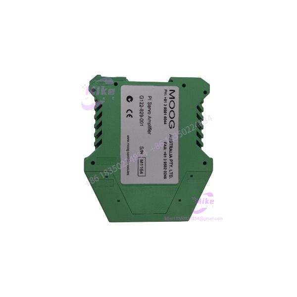
Description
Moog G122-829A001 | DIN Rail P-I Servo Amplifier, 24 VDC
Dynamic Product Introduction
The Moog G122-829A001 is not a conventional PLC analog output module. It is an analog control element intended to sit directly inside a closed-loop servo system, where command, feedback, proportional gain, and integral action must be combined before driving a hydraulic or proportional valve. Moog describes the unit as a general-purpose, user-configurable P-I servoamplifier, with internal switches allowing P, I, or P&I control.
That distinction matters during replacement. A PLC can issue a command signal, but the G122-829A001 handles the analog control loop itself, including feedback conditioning, gain adjustment, integration, optional derivative feedback, dither, enable logic, and valve-drive output. Its front-panel test points and adjustment controls were specifically intended to support commissioning and troubleshooting rather than simply provide a fixed signal conversion.
For engineers maintaining older hydraulic motion systems, this architecture is valuable because the control behavior is embedded in the amplifier configuration. Replacing it with a generic analog output card without reproducing those functions can fundamentally change loop response.
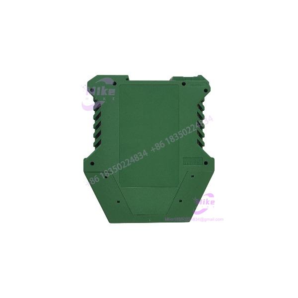
G122-829A001
Key Technical Specifications
- Model: Moog G122-829A001
- Function: P, I, or P&I control, selectable by internal switches
- Supply voltage: +24 VDC nominal
- Input 1: Scaled input with switch-selectable 55 ms lag; up to 95 V maximum at the input stage
- Input 2: Selectable 4–20 mA or ±10 V
- Feedback input: Differential 4–20 mA or ±10 V
- Feedback input resistance: 240 Ω for 4–20 mA; 100 kΩ for ±10 V
- Feedback gain: Adjustable from 1 to 10
- Feedback zero adjustment: ±10 V range
- Optional derivative feedback: Available through plug-in resistor/capacitor configuration
- Transducer excitation: +10 VDC, 10 mA maximum
- Proportional gain: 1–20 in the standard configuration; higher ranges possible through resistor selection
- Integrator gain: 1–45 per second
- Output modes: ±10 V, selectable bipolar current, or 4–20 mA
- 4–20 mA output load: Maximum 500 Ω
- Voltage output minimum load: 200 Ω
- Dither: 200 Hz, switch selectable
- Enable input: +24 V nominal
- In-position output: Available for PLC/control-system monitoring
- Mounting: Compact DIN rail enclosure
- Wiring: 0.2–2.5 mm² / approximately 24–12 AWG
- Environmental rating: IP20
- Operating temperature: 0 to 40°C
- Approximate dimensions: 100 W × 108 H × 45 D mm
- Approximate weight: 180 g
The detailed application documentation also identifies internal configuration elements such as R34 for Input 2 scaling, R17 for proportional-gain range, and R16 for derivative feedback. That is why the internal configuration of an installed unit should be documented before replacement.
Global Sourcing & Live-Test SOP
1. Inbound verification
Start with the nameplate, not the marketplace description. Confirm G122-829A001, manufacturer identification, revision information, terminal condition, DIN-rail housing, and connector/terminal integrity. Inspect the enclosure for cracks, corrosion, overheated terminals, disturbed adjustment screws, or evidence that the internal configuration has been changed.
For a used unit, photograph every front-panel adjustment and record the switch positions before applying power. This is particularly important on the G122-829A001 because the configuration is part of the control function.
2. Live power verification
Apply a controlled +24 VDC supply with appropriate current protection. Verify the supply and 0 V connections before enabling the amplifier. Check the power indicator and confirm that no abnormal current draw or heating occurs during initial energization.
3. Signal simulation
Do not connect an expensive servo valve as the first test load. Simulate the relevant command and feedback signals using calibrated equipment.
For current-loop configurations, verify 4–20 mA behavior. For voltage configurations, verify the ±10 V signal path. A calibrated process calibrator or precision signal source is preferable; use a Fluke-class DMM for independent voltage/current confirmation.
4. Control-loop verification
Test the proportional and integral functions separately where the application permits. Confirm the response to command changes, feedback polarity, bias adjustment, and output scaling.
The step push button is particularly useful during commissioning because Moog specifies it as a disturbance for closed-loop gain optimization.
5. Output verification
Measure the valve-drive output under controlled conditions. Confirm that the selected output mode corresponds to the installed valve interface—voltage, bipolar current, or 4–20 mA.
Do not assume two visually identical units have identical behavior if their internal switch and resistor configurations differ.
6. Heat and stability run
After functional testing, operate the amplifier continuously for approximately 24 hours under representative electrical loading. Monitor supply current, enclosure temperature, output stability, and any drift in the feedback or valve-drive signal.
7. Final procurement preparation
Record the tested configuration, measured outputs, revision information, and any observed adjustment positions. A replacement unit without configuration documentation is only half a spare.
Field Engineer’s Pitfall Guide
1. Do not treat the as a generic analog output card.
A field engineer may see a PLC command signal and assume the amplifier simply converts that signal into a valve current. It does considerably more. The contains the P-I control structure, feedback amplifier, gain stages, enable logic, optional derivative feedback, dither, and output amplifier.
I have seen this type of substitution create a system that technically produces the correct 4–20 mA signal but behaves completely differently once the hydraulic loop is closed. The signal can look perfect on a meter while the machine response is wrong.
2. Record internal switches and plug-in resistors before replacing the unit.
The front panel does not tell the whole story. Input selection, integrator routing, gain range, output mode, dither, feedback type, and several other functions depend on internal configuration.
Moog specifically documents selectable configurations for the feedback input, Input 2, P/I control, integrator input, output type, and dither.
If the original amplifier is still available, photograph it before removing it. Do not turn adjustment pots simply because they look accessible.
3. Do not assume it is a pin-for-pin replacement for every predecessor.
The /G122-829-001 family is associated with replacement of the earlier G122-824-002 design, but the documented replacement has a different pinout. That makes migration planning mandatory rather than optional.
During a retrofit, compare terminal-by-terminal wiring against the applicable Moog documentation. Verify command polarity, feedback polarity, valve-drive output, enable, in-position signaling, transducer excitation, and supply wiring before energizing the hydraulic circuit.
Intent-Driven FAQ
Q: What is the Moog actually used for?
A: It is a configurable analog P-I servoamplifier for closed-loop applications. It processes command and feedback signals and produces a controlled output for a servovalve or proportional valve. It is not simply a PLC analog output module.
Q: Does the support both 4–20 mA and ±10 V signals?
A: Yes. The documented configuration supports selectable 4–20 mA or ±10 V operation for Input 2 and the feedback input. The output can also be configured for ±10 V, bipolar current, or 4–20 mA.
Q: Can the run P control only?
A: Yes. Internal selector switches allow proportional control, integral control, or combined P&I operation. The appropriate configuration depends on whether the application is a position, pressure, velocity, or other closed-loop system.
Q: Is the suitable as a replacement for G122-824-002?
A: Moog documentation identifies the G122-829-001 as a functional replacement for the G122-824-002, but specifically notes a different pinout. Treat the replacement as an engineering migration: compare terminal assignments and duplicate the original control configuration before commissioning.





