


Description
Honeywell EG1033AC01 | UV Flame Amplifier
Product Introduction
A turbine flame detector has one job that leaves very little room for interpretation: determine whether combustion is actually present. The Honeywell EG1033AC01 sits in that flame-monitoring chain as an EG-series amplifier, processing the signal from a UV flame sensor and providing an electrical indication of flame status. It is associated with Honeywell’s LG/EG flame monitoring architecture used on gas turbines and compressor applications.
The operating numbers explain why this is not an ordinary signal-conditioning module. The EG1033AC01 is specified for UV detection in the approximately 180–260 nm range, with a typical flame-present response of about 0.1 second and a maximum flame-loss response of 0.2 second. Published documentation also identifies a -40 to +176°C temperature range for the EG amplifier system—a specification that needs to be interpreted carefully because the amplifier cabinet environment and sensor installation environment are not necessarily the same.
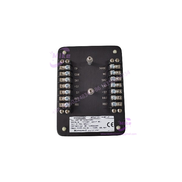
EG1033AC01
Key Technical Specifications
- Manufacturer: Honeywell
- Model: EG1033AC01
- Product Type: EG flame amplifier
- Series: LG / EG flame monitoring system
- Detection Principle: Ultraviolet flame detection
- Sensor Type: Geiger-Mueller-type phototube
- UV Detection Range: Approximately 180–260 nm
- Typical Flame-Present Response: 0.1 second
- Maximum Flame-Loss Response: 0.2 second
- DC Supply: 20–35 VDC
- Nominal Supply Reference: 28 VDC
- Maximum Power Consumption: Approximately 10 W
- Operating Temperature: -40 to +176°C, according to published EG1033AC01 specifications
- Sensor-to-Amplifier Distance: Up to approximately 330 m / 1,000 ft under specified system conditions
- Output: Flame-status hardware/relay contacts
- Mounting: Industrial installation; published listings identify DIN-rail mounting
- Approximate Shipping Weight: 3 kg
- Application: Gas turbines, power generation, compressors, and industrial combustion monitoring
Important: Published sources describe several voltage configurations across the wider EG amplifier family, including 28 VDC, 20–35 VDC, and 115 VAC. Do not assume every EG-series amplifier has the same power input. Verify the nameplate and wiring diagram for the exact EG1033AC01 before energizing a replacement.
Application Scenarios & Pain Points
Gas Turbine Flameout Protection
A turbine combustion chamber cannot be treated like a normal process instrument. If the flame disappears, the control system needs a clear signal quickly.
The is designed around this requirement, with published specifications indicating approximately 0.1 second typical flame-present response and 0.2 second maximum flame-loss response. That response behavior makes it suitable for flame-monitoring applications where delayed detection can become a turbine protection problem.
Long Sensor Runs
Long distance: Some published EG system specifications allow sensor-to-amplifier distances of approximately 330 m / 1,000 ft under appropriate installation conditions. This is useful on large turbine installations where the flame sensor cannot be mounted directly beside the control cabinet.
Short distance: The same architecture can also serve compact installations, but cable shielding, grounding, sensor alignment, and electrical noise still matter.
UV-Based Flame Discrimination
The detector architecture is aimed at ultraviolet radiation rather than simply measuring visible brightness. Published specifications identify a UV detection region around 180–260 nm, described as solar-blind and tolerant of blackbody radiation. That characteristic is particularly useful around hot turbine hardware where ordinary optical measurements can become misleading.
Legacy Turbine Controls
The harder problem is often not finding a technically similar amplifier—it is finding the exact replacement for an installed turbine monitoring circuit.
The has been identified as discontinued by some industrial parts sources, making exact-part sourcing relevant for legacy maintenance programs. Substituting a modern flame relay without checking sensor characteristics, response timing, contact logic, and supply voltage can change the behavior of the entire flame-protection chain.
Existing Site Wiring
A documented turbine schematic shows an connected into a flame-detection system with 24 VDC supply, shield connections, sensor conductors, and relay-contact outputs. That is a useful reminder for field replacement work: the amplifier is part of a complete detection circuit, not an isolated black box.
QA & Live Testing SOP
For a flame-monitoring component, simply applying power and watching an LED is not enough.
- Part-number verification: Confirm the physical label reads . Check manufacturer markings, serial information, terminal configuration, and enclosure condition.
- Origin inspection: Inspect OEM labeling, packaging, date information, and physical construction for evidence of unauthorized relabeling or substitution.
- Electrical inspection: Verify the intended supply voltage against the unit’s actual nameplate and approved wiring documentation before applying power.
- Bench power test: Energize the amplifier using a controlled DC supply appropriate for the exact unit configuration and monitor current behavior.
- Signal-path test: Verify the flame-sensor input circuit, shielding, polarity, and contact behavior according to the applicable Honeywell documentation.
- Response test: Where the correct test equipment and approved procedure are available, verify flame-present and flame-loss response behavior against the specified timing.
- Relay/contact verification: Check the output contacts independently rather than assuming a powered unit has a healthy flame-status output.
- ESD protection: Handle the amplifier in an ESD-safe environment and protect terminals and sensor connections from contamination during packaging.
- Documentation: Record the tested serial number, supply voltage, observed current, contact state, test conditions, and final disposition.
For a safety-related turbine application, do not improvise a simulated flame test on an operating turbine. Use an approved maintenance procedure and the site’s existing flame-monitoring test equipment.
Field Engineer’s Pitfall Guide
❗ Do not assume every EG amplifier uses the same power supply. Published EG-family information lists different supply configurations, while sources specifically identify the with 20–35 VDC / 28 VDC configurations. Verify the actual unit before wiring it.
❗ Do not substitute based only on physical appearance. Flame amplifiers can look remarkably similar while using different sensor inputs, supply arrangements, output logic, or response characteristics. A visually compatible enclosure does not prove electrical compatibility.
❗ Do not ignore sensor alignment and cabling. The amplifier cannot compensate for a badly positioned UV sensor, contaminated sight path, incorrect shielding, or a damaged sensor cable. If the replacement still reports flame loss, troubleshoot the complete signal chain before condemning the amplifier.
❗ Do not treat the 176°C specification as a cabinet-temperature recommendation. Published sources give the system a very wide temperature specification, but actual installation requirements depend on the equipment configuration and manufacturer’s documentation. Keep the amplifier and associated wiring within the approved installation environment.
Intent-Driven FAQ
What is the Honeywell used for?
The is an EG-series UV flame amplifier used in Honeywell LG/EG flame-monitoring systems, particularly for gas turbines and related combustion equipment. It processes UV flame-detector signals and provides flame-status outputs.
Is a PLC input module?
No. It is a dedicated flame-monitoring amplifier, not a conventional PLC/DCS analog or digital I/O card. Its function is tied directly to the flame-sensing architecture.
What voltage does use?
Published technical listings identify 20–35 VDC, with 28 VDC commonly specified for this configuration. However, the wider EG amplifier family has multiple supply configurations, so the physical nameplate and approved wiring documentation should control the installation decision.
How fast does detect flame loss?
Published specifications identify approximately 0.1 second typical flame-present response and 0.2 second maximum flame-loss response. Actual installed-system behavior depends on the sensor, wiring, test conditions, and complete flame-monitoring circuit.
What type of flame does detect?
The system is designed around ultraviolet radiation from hydrocarbon flames, with published detection around 180–260 nm. The UV approach is intended to distinguish flame radiation from ordinary thermal blackbody radiation.
Is Honeywell obsolete?
At least one established industrial parts source identifies as discontinued by the manufacturer, so it should be treated as a legacy/limited-availability component when planning procurement.
Can I replace with any UV flame amplifier?
No. This is a safety-related application, and substitution must account for sensor compatibility, supply voltage, UV response characteristics, flame-present/flame-loss timing, output contact logic, wiring, and the turbine control system’s approved architecture. A generic UV amplifier is not automatically an acceptable replacement.





