

Description
GE IS200EPSMG1A | EX2100 Exciter Power Supply Module
Product Introduction
A power-supply board in an excitation system is not a commodity component. A replacement must match the installed architecture, input source, backplane, and required output rails—not simply fit the available slot.
The GE IS200EPSMG1A is an Exciter Power Supply Module used in GE’s EX2100 excitation control system. It receives 125 VDC from the EPDM power-distribution module and generates the regulated DC power required by control electronics and associated excitation equipment. The EPSM uses a buck-regulator and push-pull inverter power-conversion arrangement.
For maintenance teams sourcing this legacy GE board, the important checks are exact revision, backplane compatibility, and evidence of functional testing. A matching model number is the starting point—not proof of drop-in compatibility.
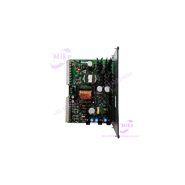
IS200EPSMG1A
Key Technical Specifications
- Manufacturer: General Electric
- Model: IS200EPSMG1A
- Functional Acronym: EPSM
- Series: EX2100 Excitation Control
- Board Function: Exciter power supply
- Input Power: 125 VDC supplied from EPDM
- DC Output Rails: +5 VDC, ±15 VDC, +24 VDC, per applicable system configuration
- Power Conversion: Buck regulator and push-pull inverter
- Backplane: EPBP exciter power backplane
- Associated Module: EPDM power-distribution module
- Reference Documentation: GEI-100462 and GEH-6632
- Installation Role: Supplies power to excitation control electronics and designated external modules
Output loading, connector pin assignments, protection characteristics, and allowable input tolerances should be verified against the applicable GE documentation and installed system configuration. Do not infer them from the model number alone.
Global Sourcing & Live-Test SOP
1. Inbound Verification
- Photograph the complete GE nameplate and all board markings.
- Confirm the exact IS200EPSMG1A part number.
- Record the revision, serial number, and any suffixes or assembly markings.
- Inspect PCB edges, connectors, components, and mounting points for damage or repair evidence.
- Check for corrosion, contamination, heat discoloration, or damaged components.
- Confirm that the supplied board matches the buyer’s original configuration.
2. Controlled Power-Up
- Test only with the correct EX2100-compatible test arrangement and documented input conditions.
- Verify the required input source and polarity before energizing.
- Do not apply 125 VDC directly unless the test procedure specifically calls for it.
- Monitor startup behavior and output rails using appropriate test equipment.
- Compare measured values against GE specifications for the applicable board revision.
3. Output and Functional Checks
- Verify the required DC output rails under the approved test load.
- Check for abnormal ripple, instability, or unexpected voltage drop.
- Inspect for overheating, unusual odor, or intermittent startup.
- Where a compatible EX2100 test rack is available, verify operation in the intended backplane configuration.
- Record measured results and any fault conditions.
4. Extended Heat Run
For units sold as tested, perform an extended powered run under an approved test setup.
Monitor:
- Output voltage stability
- Startup and restart behavior
- Thermal behavior
- Intermittent faults
- Connector and backplane contact condition
Record test duration, input conditions, output measurements, and the test configuration. Do not advertise a unit as load-tested or fully functional unless those checks were actually completed.
5. Final Preparation
- Record the exact model, revision, and serial number.
- Photograph the board before packaging.
- Use ESD-safe packaging and protect connectors from impact.
- Include available test documentation and traceability records.
- Clearly disclose whether the item is tested, untested, repaired, or sold as-is.
Field Engineer’s Pitfall Guide
❗ Revision compatibility is not automatic
The IS200EPSMG1A revision must be checked against the installed EX2100 configuration. A matching base model does not establish backward compatibility with other revisions or related EPSM boards. Confirm the approved replacement path in GE documentation before installation.
❗ Do not confuse EPSMG1 and EPSMG2 applications
EPSMG1 serves the excitation-control power architecture, while EPSMG2 serves the regulator-control application. Related boards may share naming conventions but are not automatically interchangeable. Verify the complete board number and system location.
❗ Treat the input as a system power source—not a bench-supply assumption
The board is designed to receive 125 VDC from the EPDM power-distribution module. Incorrect test connections or an improvised supply arrangement can damage the board or create a hazardous condition. Use the GE-approved procedure and qualified personnel.
Intent-Driven FAQ
What is the GE IS200EPSMG1A?
The is a GE Exciter Power Supply Module. It converts 125 VDC from the EPDM into regulated DC rails used by excitation-system control electronics.
Is the a PLC module?
No. It is a power-supply board for GE’s excitation control system, not a standalone PLC CPU or general-purpose I/O module.
What input voltage does the use?
The documented EPSMG1 architecture receives 125 VDC from the EPDM power-distribution module. Verify the system wiring and applicable GE documentation before testing or installation.
What are the output voltages?
Published supplier documentation identifies +5 VDC, ±15 VDC, and +24 VDC rails. Confirm output requirements, ratings, and tolerances against the relevant GE manual and board revision before commissioning.
Can the replace another EPSM board?
Not based on appearance or family name alone. Confirm the complete part number, revision, system role, and GE-approved compatibility information.
Is the obsolete?
It is a legacy control-system component commonly encountered through industrial surplus and replacement-part channels. Current availability and condition depend on individual suppliers; confirm stock and test status at the time of purchase.
What should I verify before purchasing?
Request clear photos of the nameplate and board markings. Confirm the exact model, revision, physical condition, included hardware, and test status. For a running excitation system, verify compatibility with the installed EPBP/EPDM arrangement before committing to the replacement.
Bottom Line for Buyers
The is an Exciter Power Supply Module intended for a specific excitation-control power architecture. Its value as a replacement depends on exact revision, proper backplane fit, and verified operation—not merely a matching label.
Before purchasing, confirm the complete part number, board revision, test status, and compatibility with the installed configuration. Treat unverified surplus stock as untested until the seller provides meaningful inspection or test evidence.





