

Description
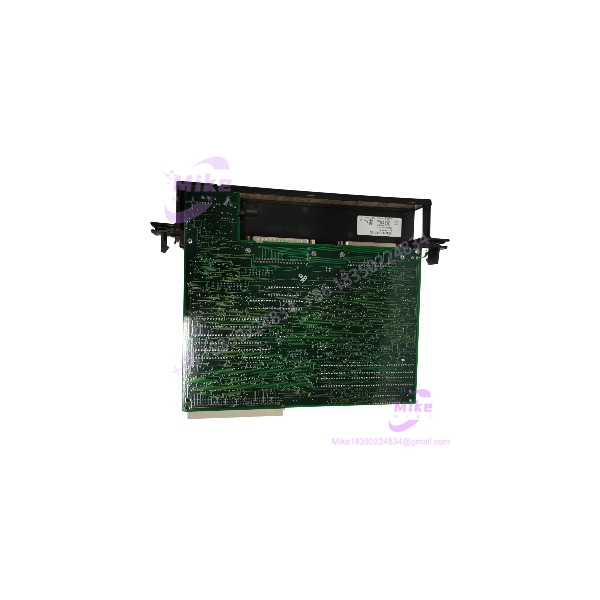
GE Fanuc IC697RCM711 | Series 90-70 Redundancy Module
Product Introduction
A redundant PLC architecture is only useful if the backup controller has the information it needs to assume control. The GE Fanuc IC697RCM711 provides the communications path for synchronization messages and shared I/O data between the active and backup CPUs in a Series 90-70 Hot Standby system.
The IC697RCM711 is installed in both the primary and secondary PLCs. Its high-speed parallel communications interface supports an effective data rate of 500 KB/s over an interconnect distance of up to 50 ft (15 m). For legacy process systems, this module is a dedicated redundancy component—not a general-purpose communications card. Replacement planning must account for the paired RCM, CPU family, rack placement, and correct interconnect cable.
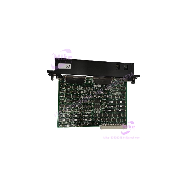
IC697RCM711
Key Technical Specifications
- Catalog Number: IC697RCM711
- Product Family: GE Fanuc Series 90-70
- Module Description: Redundancy Communications Module
- System Role: Hot Standby CPU redundancy synchronization and I/O-data transfer
- Module Width: Single slot
- Required Location: Rack 0; no empty slot between the CPU and RCM
- Compatible CPU Families: Series 90-70 redundancy-compatible CPUs, including IC697CPU780 and applicable CGR CPUs
- Communications Interface: High-speed parallel redundancy link
- Effective Data Rate: 500 KB/s
- Maximum Cable Length: 50 ft (15 m)
- Electrical Isolation: Non-isolated differential communication
- Backplane Current Requirement: 1.2 A at 5 VDC, per GE datasheet
- Status Indicators: Board OK, Local Ready, Local Active, Remote Ready, Remote Active
- Manual Control: Front-panel pushbutton to request transfer to the backup unit when it is ready
- Configuration: Configured as part of the Series 90-70 Hot Standby redundancy system
- Required System Components: Matching RCM in the paired PLC, compatible CPUs, and appropriate redundancy interconnect cabling
- Expansion Rack Connection: Link arrangement depends on whether the opposite PLC uses a single rack or expansion racks
The GE Fanuc redundancy documentation identifies the IC697RCM711 as the communications path between redundant CPUs and specifies the 50-ft cable limit and 500 KB/s effective data rate.
Global Sourcing & Live-Test SOP
An RCM should not be considered verified solely because its Board OK indicator illuminates. Functional confidence depends on testing within a compatible redundancy setup.
Incoming Verification
- Confirm the IC697RCM711 catalog number and complete revision suffix.
- Inspect the housing, backplane connector, interconnect connector, and front-panel indicators.
- Check for damaged contacts, corrosion, heat discoloration, or signs of electrical stress.
- Confirm whether the listing includes only the RCM or also includes interconnect cables and related hardware.
Authenticity & Traceability
- Photograph the OEM label, catalog number, and revision markings.
- Record serial/date-code information where available.
- Compare identifying details with available GE Fanuc documentation.
- Classify the unit accurately as new surplus, used, or refurbished.
Functional & Redundancy Test
- Install the module in a compatible Series 90-70 redundancy test rack.
- Verify startup behavior and Board OK status.
- Confirm correct rack placement and cable connection.
- Test with a compatible paired CPU and RCM configuration where available.
- Verify Local Ready and Remote Ready indications under appropriate conditions.
- Where the test setup supports it, confirm synchronization and shared I/O-data exchange.
- Test manual transfer only under a controlled redundancy test procedure.
- Record the test configuration and functions actually verified.
Extended Run & Test Record
- Perform an extended powered run when test facilities permit.
- Record actual test duration, CPU type, RCM revision, cable arrangement, and observed diagnostics.
- Clearly identify any redundancy or switchover functions not tested.
- Do not claim a 24-hour heat run unless completed and documented.
ESD-Safe Packaging
- Use ESD-protective packaging and suitable cushioning.
- Protect the backplane and interconnect connectors against impact and contamination.
- Secure the module against movement during transit.
Field Engineer’s Pitfall Guide
- ❗ An RCM is required in both PLC units. A single does not establish a redundant pair. Confirm the matching RCM in the primary and secondary systems, along with the compatible CPU family and redundancy configuration.
- ❗ Rack placement is part of the design. The RCM must reside in rack 0, with no empty slot between it and the CPU. Other modules may be located between them, but an empty slot is not permitted. Verify the installed rack layout before commissioning.
- ❗ Do not exceed the redundancy-link cable limit. GE documentation specifies a maximum cable length of 50 ft (15 m). The link is a non-isolated differential interface; use the specified redundancy cabling and follow the system manual rather than substituting generic communications cable.
Intent-Driven FAQ
Q1: What is the GE Fanuc used for?
It is a Redundancy Communications Module for Series 90-70 Hot Standby systems. It provides the link used to synchronize primary and backup CPUs and transfer shared I/O data.
Q2: Do I need two modules for a redundant system?
Yes. The primary and secondary PLCs each require an RCM for the redundancy communications link.
Q3: What is the maximum cable distance?
The documented maximum is 50 ft (15 m). Use the appropriate redundancy interconnect cable and follow the system configuration requirements.
Q4: Does the support manual switchover?
The module has a front-panel pushbutton used to request transfer to the backup unit when it is ready. Switchover should be performed only under the system’s approved operating procedure.
Q5: Can I use the as a general-purpose communications module?
No. It is designed for redundancy communications in a Series 90-70 Hot Standby architecture, not as a general-purpose serial or Ethernet interface.
Q6: Can the be hot-swapped?
Do not assume live removal or insertion is permitted. Follow the applicable Series 90-70 redundancy-system procedures and site lockout requirements. A redundancy system’s ability to remain operational during certain faults does not establish that this module is safe to remove under power.
Q7: What should I verify before ordering a replacement?
Confirm the catalog number and revision, CPU compatibility, matching RCM in the paired PLC, rack placement, cable type and length, condition classification, functional-test coverage, and written warranty terms.





