


Description
GE Fanuc 8811-IO-DC | PAC8000 Discrete I/O Module
Architect’s Product Breakdown
The GE Fanuc 8811-IO-DC operates as an advanced discrete digital input/output module engineered within the PAC8000 modular I/O framework. Designed for heavy industrial automation, hazardous process environments, and safety-related control architectures, it coordinates the rapid interchange of 24 VDC discrete signals between field sensors (such as limit switches, proximity detectors, and pushbuttons) and the central controller.
Mounting directly onto standard PAC8000 system carriers, the module interfaces with field wiring through dedicated terminal blocks, allowing maintenance staff to hot-swap electronic units instantly without rewiring field loops. Its robust internal optical isolation and diagnostic capabilities protect control loops against high-voltage transients and grounding anomalies common in heavy switchgear spaces.
Deploying an authentic 8811-IO-DC module ensures strict hardware compatibility, predictable timing loops, and reliable long-term performance across demanding process control networks.
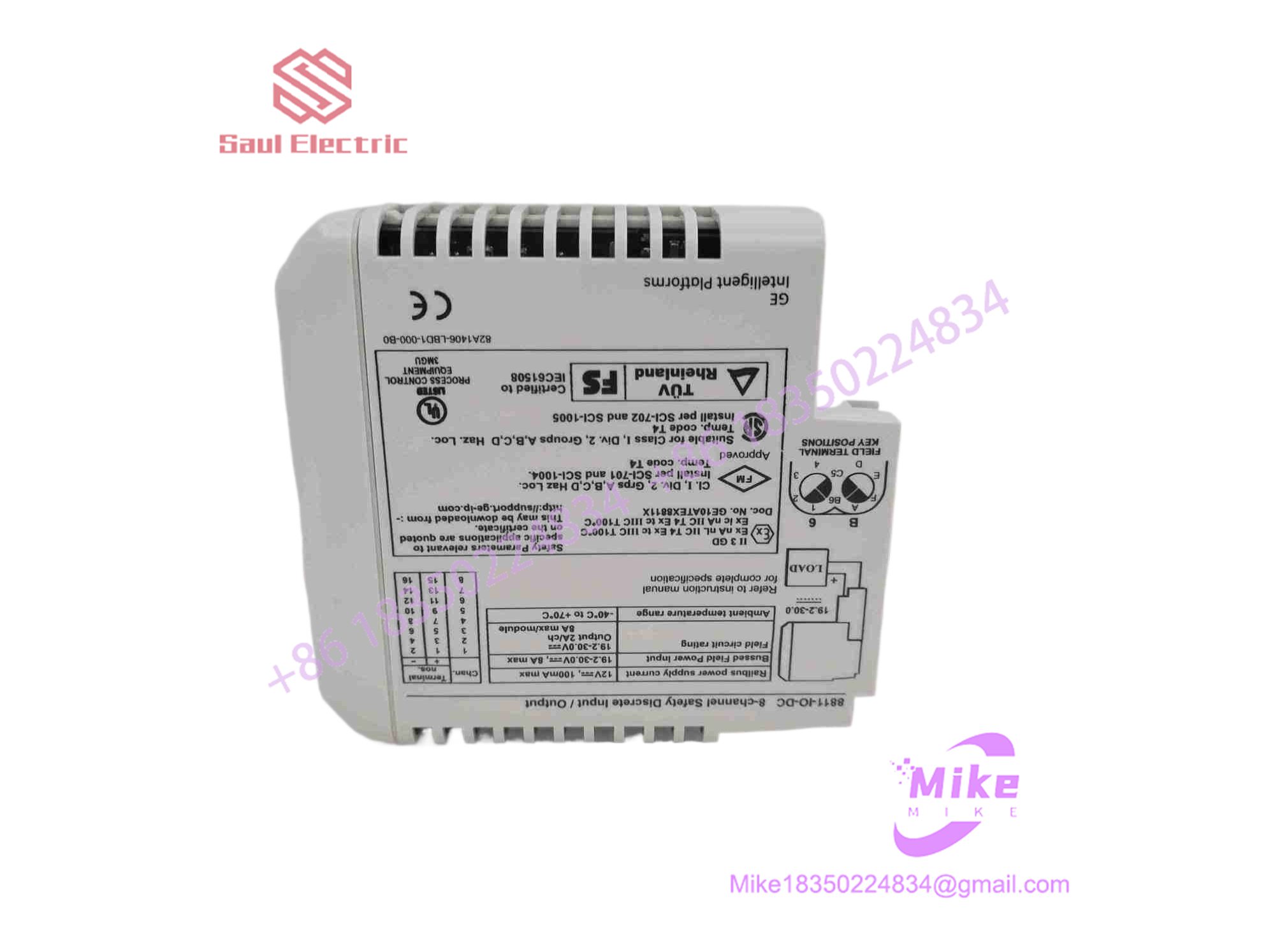
8811-IO-DC
Key Technical Specifications
| Parameter | Technical Specification |
| Module Type | Discrete Digital Input/Output (I/O) Module |
| System Compatibility | GE Fanuc PAC8000 / SafetyNet Modular I/O Platform |
| Operating Voltage | 24 VDC nominal field supply range |
| Channel Configuration | Configurable digital lines for status reading and switching |
| Isolation | Channel-to-bus galvanic isolation |
| Power Consumption | Low-power solid-state internal rail draw |
| Operating Temperature | -20°C to +70°C (-4°F to +158°F) standard industrial range |
| Physical Weight | ~0.5 kg to 1.0 kg (approximate standard format) |
Field Engineer’s Pitfall Guide
- WARNING: Incorrect Field Supply Polarity. Reversing the 24 VDC external loop power polarity can cause module logic failure or blow onboard protection elements. Verify DC rail polarity prior to system energization.
- WARNING: Inductive Load Back-EMF. Driving unsuppressed inductive loads (such as heavy solenoids or relays) directly through digital output lines without flyback diodes can damage internal switching transistors.
- WARNING: Live Carrier Pin Misalignment. When inserting the module onto a carrier backplane, ensure absolute vertical alignment. Forcing an unaligned unit can bend backplane interface pins and ruin ground continuity.
QA & Testing SOP (Transparency)
- Visual & Origin Verification: Detailed physical inspection of OEM identification plates, part number tags (8811-IO-DC), conformal coating integrity, and connector pin cleanliness.
- Bench Power & Diagnostic Handshake: Modules are mounted on an isolated PAC8000 test carrier, powered via a regulated DC source, and verified for clean internal microprocessor boot behavior and status LED execution.
- Digital I/O Simulation: Technicians inject simulated 24 VDC input states and exercise output switching channels to validate optical isolation, response latency, and threshold switching accuracy.
- Final Packaging: Non-volatile status registers are cleared, and the unit is sealed in an anti-static moisture barrier bag before being packed inside high-density industrial foam containers.
Technical FAQ
Can I hot-swap this digital I/O module while the process system is live?
Yes. The PAC8000 architecture supports hot-swapping electronic modules under power, provided local plant safety policies and system configuration guidelines permit live replacement.
Does this module provide internal power to field sensors?
The module relies on bussed system power rails distributed through the carrier backplane to supply necessary operating and loop potentials, subject to system design configurations.
Are configuration parameters saved during a total power loss?
Yes. Module configuration maps, channel logic assignments, and operational states are retained securely within non-volatile internal memory through complete power interruptions.
What causes a channel status LED to flash or fail to register?
A non-responsive channel is typically caused by a blown field loop fuse, loose terminal block screw torque, an open-circuit sensor wire, or an incorrect threshold configuration in the controller software.





