


Description
GE DS200DCFBG1BGB | Mark V DCFB Board, In Stock
Architect’s Product Breakdown
The GE DS200DCFBG1BGB functions as a core DC Feedback (DCFB) board within the legacy Mark V Speedtronic turbine and excitation control architecture. Its primary operational role is to sample, isolate, and scale critical analog feedback variables—such as field voltage and current—before routing them back to the main control processor. By handling precise analog conditioning right at the rack level, the board protects downstream processors from high-voltage transients while maintaining the strict loop accuracy required for turbine excitation regulation.
Deploying this module requires strict attention to hardware revision suffixes. Moving between different group revisions (such as shifting from an earlier ‘A’ suffix to the ‘BGB’ iteration) can introduce subtle changes in component placement, jumper configurations, or internal bus communication timing. When replacing a failed card in an active generation plant, engineers must verify that the installed firmware and jumper configurations mirror the exact plant drawing specifications to prevent regulatory loop instability or controller fault trips.
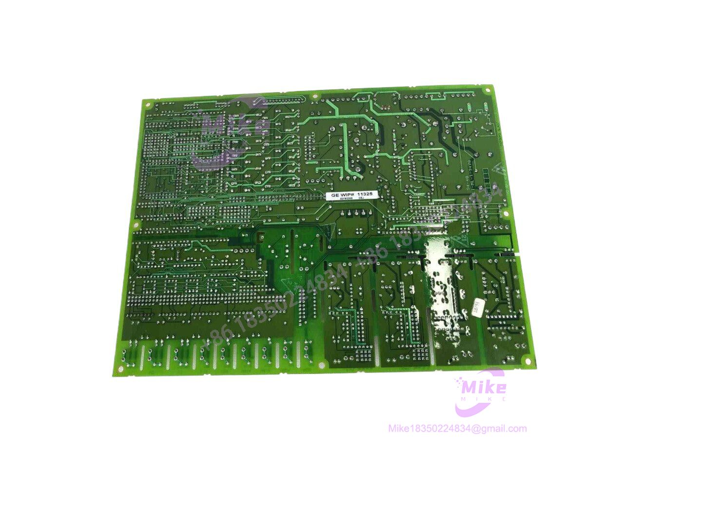
DS200DCFBG1BGB
Key Technical Specifications
| Parameter | Specification |
| Series | GE Mark V Speedtronic / Excitation |
| Module Type | DC Feedback Board (DCFB) |
| Input Signals | High-voltage DC field voltage and current feedback |
| Processing Interface | Ribbon cable headers and plug-in edge connectors |
| Mounting | Rack-mounted card slot within core control enclosure |
| Operating Temperature | 0°C to +65°C |
| Environmental Protection | Factory conformal coating against humidity and corrosive gases |
| Diagnostic Indicators | On-board status LEDs for power and communication health |
Field Engineer’s Pitfall Guide
- WARNING: Unsecured Ribbon Cable Snapping. The delicate ribbon cable connectors linked to the DCFB board become brittle over decades of continuous exposure to cabinet heat. Pulling the cables forcefully during replacement will sheer internal conductors.
- WARNING: Jumper and Suffix Mismatch. Failing to replicate the exact hardware jumper positions from the failed unit onto the new DS200DCFBG1BGB board can skew feedback scaling, leading to excitation control alarms or immediate unit lockouts.
- WARNING: Electrostatic Discharge Vulnerability. Handling the board without proper grounding straps in dry control rooms can permanently compromise sensitive analog isolation optocouplers.
- Field Anecdote: I remember a 3 AM callout where a plant lost a combined-cycle gas turbine because a technician swapped a DCFB board without matching the revision-specific jumper settings, sending an unscaled voltage feedback signal that instantly tripped the excitation system on over-excitation limits.
QA & Testing SOP
- Visual & Origin Verification: Inspect the printed circuit board under optical magnification for trace micro-fractures, component bulging, and verify original GE manufacturing labels and revision codes.
- Live Test Bench Environment: Mount the card onto a certified Mark V static test rack equipped with isolated variable power supplies.
- Diagnostics & Signal Calibration: Inject calibrated reference DC voltages into the input channels, verify linear analog scaling across the processing path, and check diagnostic handshakes over the control bus.
- Anti-Static Packaging: Wrap the tested unit in high-shielding anti-static materials and pack with high-density corrugated foam to protect edge fingers and connectors during transit.
Technical FAQ
Can I use the DS200DCFBG1BGB as a drop-in replacement for earlier ‘A’ suffix revisions?
Compatibility depends on the specific system revision and software build. While physical dimensions match, minor circuit changes on ‘B’ series boards may require firmware or configuration updates on the host controller.
Does this board store persistent program logic or configuration parameters?
No. The DCFB card is a dedicated analog conditioning and feedback interface; it does not store control code or non-volatile user configurations locally. All logic resides on the central Mark V controller.
What causes drift in analog feedback readings on this module?
Aging electrolytic capacitors and resistor tolerance shift from prolonged thermal cycling in unconditioned turbine enclosures are the primary drivers of analog calibration drift over time.
Is this board hot-swappable while the excitation system is energized?
No. Hot-swapping the DS200DCFBG1BGB while power is applied risks severe electrical arcing on the backplane edge pins and can corrupt sensitive analog input channels on neighboring rack modules.





