


Description
Foxboro FBM204 | 0 to 20 mA Analog I/O Module
Product Introduction
A mixed analog I/O card becomes a wiring problem long before it becomes a software problem. The Foxboro FBM204 addresses that requirement by combining four independent 20 mA DC analog input channels with four independent 20 mA DC analog output channels in one Fieldbus Module. Each channel is galvanically isolated from the other channels and from ground, which is particularly useful when field instruments do not share a clean electrical reference.
The FBM204 accepts signals such as 4–20 mA transmitter outputs or self-powered 20 mA sources on its input channels, while its four output channels provide 0–20 mA current to external loads. The module performs signal conversion between field wiring and the optionally redundant 2 Mbps module Fieldbus. Schneider Electric specifies independent Sigma-Delta conversion for the analog inputs, with new input readings available every 25 ms and a software-configurable integration period for noise and power-line frequency rejection.
This is not simply an eight-channel current card. The FBM204 also supports configurable conversion time, fail-safe Hold/Fallback behavior, analog output fallback data, Rate of Change Limits, and DPIDA control-block execution for applications requiring control processing closer to the I/O layer.
For migration work, the distinction between the FBM204 and its wiring infrastructure matters. Schneider documentation specifically identifies the FBM204 as a replacement for the 100 Series FBM04 and allows appropriate existing FBM04 termination assemblies or a Termination Assembly Adapter to be used for the field wiring.
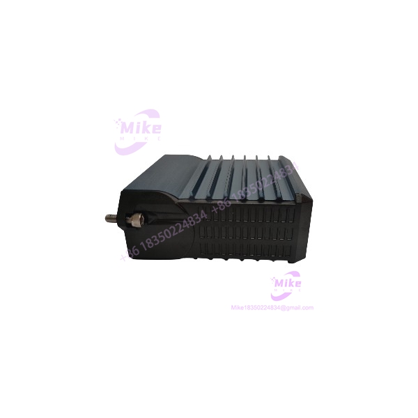
FBM204
Key Technical Specifications
- Module: Foxboro
- Function: 0 to 20 mA analog input/output interface
- Analog Inputs: 4 independent channels
- Analog Outputs: 4 independent channels
- Nominal I/O Range: 0 to 20.4 mA DC
- Input Accuracy, Including Linearity: ±0.03% of span
- Output Accuracy, Including Linearity: ±0.03% of span
- Accuracy Temperature Coefficient: ±50 ppm/°C
- Input Impedance: 61.5 Ω nominal
- Input Conversion: Independent Sigma-Delta converter per channel
- Input Integration Period: Software configurable
- Input Common-Mode Rejection: >100 dB at 50/60 Hz
- Input Normal-Mode Rejection: >95 dB at 50/60 Hz
- Maximum Output Load: 750 Ω
- Output Processing Delay: 30 ms maximum
- Output Resolution: 13 bits
- Fieldbus: Redundant 2 Mbps module Fieldbus
- Fieldbus Paths: Path A and Path B supported
- Channel Isolation: Galvanically isolated channel-to-channel and channel-to-ground
- Isolation Withstand: 600 VAC for one minute between channels or channel and ground
- Supply Voltage: 24 VDC, +5% / -10%, redundant
- Power Consumption: 7 W maximum
- Heat Dissipation: 3.5 W maximum
- Operating Temperature: -20 to +70°C (-4 to +158°F)
- Storage Temperature: -20 to +70°C (-4 to +158°F)
- Relative Humidity: 5–95%, noncondensing
- Altitude, Operating: -300 to +3,000 m
- Altitude, Storage: -300 to +12,000 m
- Vibration: 0.75 g from 5 to 500 Hz
- Environmental Classification: ISA S71.04 Class G3 harsh environment
- Module Weight: Approximately 284 g
- Dimensions: 102 × 45 × 104 mm; 114 mm high including mounting lugs
- Module Part Number: RH914SY
- Termination Cable Length: Up to 30 m
- Cable Types: Polyurethane or LSZH
- Baseplate Connector: 37-pin D-subminiature
- Termination Assembly Connector: 25-pin D-subminiature
Analog Input Architecture
Each of the four input channels operates independently. The module accepts current-loop signals including conventional 4–20 mA transmitter signals and self-powered 20 mA sources.
The 61.5 Ω nominal input impedance should be included in the loop-budget calculation when determining transmitter compliance voltage and maximum cable distance. Schneider specifies approximately 20.2 VDC compliance voltage at 20.4 mA for the input side; actual field-device distance still depends on transmitter capability, wire gauge, and voltage drop elsewhere in the loop.
The input channels incorporate current limiting and voltage regulation. Each channel is galvanically isolated, and the design limits normal analog input current to less than 30 mA. This architecture is useful for mixed-field installations where ground potential differences or channel interaction would otherwise complicate troubleshooting.
Analog Output Architecture
The four output channels generate 0–20 mA signals for external loads. Schneider specifies a maximum load of 750 Ω and a maximum output processing delay of 30 ms.
The output stage is current limited and voltage regulated, with channel-to-channel galvanic isolation. The normal output design limits current to approximately 25 mA; Schneider notes that an output FET short could permit current to rise to approximately 35 mA.
The outputs are also electrically compatible with standard HART signaling. They meet the impedance requirements for a HART high-impedance device and can operate in a HART loop without interfering with HART communication between the field device and handheld communicator. When a FoxCom or HART transmitter is used as an input device to the , Schneider specifies a 200 Ω series resistor, assembly RH902VY.
For maintenance-intensive applications, the RH917QW termination assembly provides built-in bypass jacks for each output channel. These can be used with the Foxboro DCS Output Bypass Station or another external 20 mA source when maintaining output signals during module maintenance is a requirement.
Fieldbus and Control Processing
The communicates with its associated control processor through the redundant 2 Mbps module Fieldbus. It can accept communication through either Fieldbus path A or B; if one path becomes unsuccessful or the system switches paths, communication continues through the active path.
The module executes an Analog I/O application program supporting configurable conversion time, fail-safe configuration, Analog Output Fail-Safe Fallback Data, and Rate of Change Limits.
A further capability is DPIDA support. Where the appropriate Foxboro software and system architecture are installed, the FBM can execute a distributed PIDA application to provide a fast control loop at the I/O level. That function should be verified against the target controller, software revision, and site configuration before being treated as an available feature in a replacement project.
Mounting, Termination, and Wiring
The mounts on a 200 Series baseplate. The baseplate can be DIN-rail mounted horizontally or vertically, or mounted horizontally in a 19-inch rack using the appropriate mounting hardware. Schneider also documents mounting the on a 100 Series conversion mounting structure for migration applications.
Field signals connect through DIN-rail termination assemblies. Schneider lists compression and ring-lug termination options, including:
- RH916XK / P0916AH: termination options with compression or ring-lug configurations
- RH917QW: Termination assembly with output bypass capability
- Termination Cable: Up to 30 m
- Cable Construction: Polyurethane or LSZH
- Cable Interface: 37-pin D-sub at FBM baseplate and 25-pin D-sub at termination assembly
For a procurement replacement, the termination assembly must be matched to the existing cabinet wiring and certification requirements rather than selected solely from the FBM model number.
Global Sourcing & Live-Test SOP
1. Inbound Verification
- Confirm the nameplate reads and verify the module part number where visible.
- Record the module serial number, manufacturing information, and hardware revision.
- Compare the physical label against the purchase order and OEM documentation.
- Inspect the enclosure, mounting lugs, connectors, LEDs, and terminal interfaces for damage.
- Verify that the module is not being confused with FBM201, FBM205, FBM208, or other Foxboro analog modules.
- For used or surplus equipment, document all visible wear before testing.
- Trace available OEM documentation and procurement paperwork where required for customs, asset history, or customer QA records.
2. Live Simulation
A proper test rack should reproduce the electrical conditions expected in the application.
- Feed controlled current signals into all four analog input channels.
- Verify representative 4 mA, 12 mA, and 20 mA points.
- Simulate transmitter loop behavior and confirm input scaling.
- Drive representative output loads within the 750 Ω maximum specification.
- Check each analog output independently across multiple setpoints.
- Verify channel isolation where the test equipment permits.
- Exercise fail-safe Hold/Fallback behavior only when the associated configuration and control environment are available.
- Validate HART-related loop behavior when HART instrumentation is part of the intended application.
3. Diagnostics
- Confirm front-panel status LEDs behave consistently with the system state.
- Verify redundant Fieldbus path communication where the test rack supports both paths.
- Check controller-to-FBM communication and I/O data integrity.
- Monitor analog input stability during a sustained test.
- Check output response and processing delay against the application requirement.
- Record firmware/software compatibility information where available.
- Investigate abnormal current draw, communication errors, channel drift, or intermittent Fieldbus behavior before release.
4. Final Preparation
- Record serial number and test results in the inspection report.
- Photograph the identification label for traceability.
- Package the module in ESD-safe material.
- Protect connectors and mounting hardware against impact.
- Preserve the termination assembly configuration when supplied as part of the package.
- Do not represent a used or refurbished as factory-new unless its condition and documentation substantiate that claim.
Field Engineer’s Pitfall Guide
❗ Do not confuse 600 VAC withstand with an allowable field input voltage. The can withstand 600 VAC for one minute during the specified isolation test, but Schneider explicitly states that the channels are not intended for permanent connection to hazardous voltage circuits. Applying more than 30 VAC or 60 VDC to the channels violates the stated electrical safety requirements.
❗ Do not calculate loop distance from cable length alone. The 61.5 Ω input impedance, transmitter compliance voltage, wire resistance, and field-device voltage requirements all contribute to the actual loop budget. On the output side, the 750 Ω maximum load is equally important when checking whether a remote actuator, positioner, or signal receiver can be driven correctly.
❗ Do not replace a 100 Series FBM04 by simply matching the channel count. The can serve as a migration replacement for the FBM04, but the termination strategy must be checked. Schneider specifically documents use of appropriate FBM04 termination assemblies or a Termination Assembly Adapter, so cabinet wiring should be verified before the replacement module is installed.
Intent-Driven FAQ
1. What is the Foxboro used for?
The is a mixed analog I/O Fieldbus Module with four 0–20 mA analog inputs and four 0–20 mA analog outputs. It interfaces field current signals with the Foxboro DCS through the redundant 2 Mbps module Fieldbus.
2. Is the a 4-channel or 8-channel module?
It has eight analog channels total: four inputs and four outputs. It should not be described as eight analog inputs or eight analog outputs.
3. Does the support 4–20 mA signals?
Yes. The input channels can accept typical 4–20 mA transmitter signals, while the specified nominal I/O range is 0–20.4 mA DC. The outputs provide a 0–20 mA signal range.
4. Is the HART compatible?
Yes. Schneider specifies HART compatibility for the output channels. When a FoxCom or HART transmitter is used as an input device, a 200 Ω series resistor, RH902VY, is specified for the application.
5. What is the module part number?
The Schneider Electric PSS identifies the module part number as RH914SY. The termination assembly has separate part numbers and should be matched to the required wiring configuration.





