


Description
Foxboro FBM201 | 8-Channel Analog Input Module
Product Introduction
When an I/A Series control loop starts drifting, the first question is not whether the PLC/DCS database still contains the correct tag. It is whether the physical input channel is actually measuring the transmitter signal correctly. The Foxboro FBM201 addresses that interface layer with eight isolated analog input channels designed for process measurements in the I/A Series 200 architecture.
The standard FBM201 accepts 0–20 mA DC signals. Its FBM201 family also includes variant suffixes for voltage and millivolt applications: FBM201b supports 0–100 mV, FBM201c supports 0–5 V, and FBM201d supports 0–10 V DC. These are distinct variants, not interchangeable input configurations.
The module communicates with its associated Fieldbus Communication Module or Control Processor through the redundant 2 Mbps module Fieldbus. Each of the eight analog channels is galvanically isolated from the other channels and from ground, making the FBM201 suitable for multi-loop process instrumentation where channel-to-channel isolation matters.
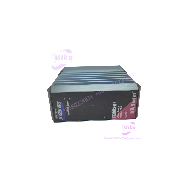
FBM201
Key Technical Specifications
- Model: FBM201
- Product type: Analog Input Interface Module
- System: Foxboro I/A Series 200
- Number of channels: 8
- Channel type: Isolated, independent analog inputs
- Standard input range: 0–20 mA DC
- FBM201b input range: 0–100 mV DC
- FBM201c input range: 0–5 V DC
- FBM201d input range: 0–10 V DC
- Analog accuracy, including linearity: ±0.03% of span
- Accuracy temperature coefficient: ±50 ppm/°C
- Input impedance, current version: 61.5 Ω nominal
- A/D conversion: Independent Sigma-Delta converter per channel
- Integration period: Software configurable
- Common-mode rejection: >100 dB at 50/60 Hz
- Normal-mode rejection: >95 dB at 50/60 Hz
- Channel isolation: Galvanically isolated channel-to-channel and channel-to-ground
- Isolation withstand: 600 VAC for one minute between channel/ground or channel/channel
- Communication: Redundant 2 Mbps module Fieldbus
- Fieldbus interface: Associated FCM or FCP
- Mounting: I/A Series modular baseplate
- Termination: Dedicated termination assemblies
- Operating temperature: -20 to +70°C
- Storage temperature: -40 to +70°C
- Operating humidity: 5–95%, noncondensing
The electrical specifications above are based primarily on Schneider Electric’s current PSS 41H-2S201 documentation.
Input Architecture
The standard provides eight 0–20 mA analog inputs. Each channel has its own signal conversion path and galvanic isolation, which is particularly useful when transmitter grounds, cabinet wiring, or external instrumentation introduce different electrical potentials.
The module uses an independent Sigma-Delta converter for each channel. Software-configurable integration allows the control system to balance response speed against process noise rather than relying solely on external signal conditioning.
For procurement, do not collapse the entire family into one electrical specification:
- — 0–20 mA DC
- FBM201b — 0–100 mV DC
- FBM201c — 0–5 V DC
- FBM201d — 0–10 V DC
A suffix mismatch can therefore turn an apparently correct replacement into an electrically incompatible installation.
System Communication
The belongs to the I/A Series 200 FBM architecture. It communicates with an associated FCM or FCP through the redundant 2 Mbps module Fieldbus.
The redundant communication arrangement allows the to accept communication through either Fieldbus path. If one path becomes unavailable or the system switches at the control level, the module can continue through the active path.
The module itself should therefore be evaluated as part of the complete subsystem:
Field transmitter → Termination Assembly → → redundant 2 Mbps Fieldbus → FCM/FCP → I/A Series control environment
The termination assembly and termination cable are part of the practical replacement equation. Do not assume that the module alone represents the complete field interface.
Global Sourcing & Live-Test SOP
Inbound Verification
For an received from surplus, refurbishment, or legacy inventory, verify:
- Exact FBM designation
- Suffix: / 201b / 201c / 201d
- OEM label and manufacturer markings
- Serial number
- Hardware revision
- Connector condition
- Baseplate interface condition
- Evidence of corrosion or contamination
- Matching termination assembly/cable requirements
Where possible, record the original Foxboro/Invensys part number associated with the physical unit. P0914SQ is associated with in Foxboro documentation and inventory records, but the exact procurement part number should still be confirmed against the unit label and project documentation.
Live Simulation
A proper test rack should reproduce an actual 0–20 mA transmitter environment.
Recommended verification:
- Apply calibrated 0 mA input
- Apply intermediate current values
- Apply full-scale 20 mA
- Verify each of the eight channels independently
- Check channel-to-channel isolation
- Confirm correct scaling in the DCS configuration
- Check Fieldbus communication through both redundant paths
- Verify diagnostic status
- Confirm stable readings after integration/filter settings are applied
A Fluke-class precision current source or equivalent calibrated loop simulator is appropriate for this type of validation. The objective is not merely to see whether the module powers up; it is to establish that the analog conversion path and Fieldbus data path both behave correctly.
Diagnostics
Check:
- Module operational LEDs
- Fieldbus communication status
- Channel signal values
- Channel scaling
- Input loop current
- Termination integrity
- Configuration database compatibility
- Redundant Fieldbus path behavior
- Abnormal diagnostic indications
A module that boots successfully but produces incorrect process values should not be released as tested.
Final Preparation
Before shipment:
- Record serial number and hardware revision
- Record tested input range
- Photograph connectors and labels
- Protect the Fieldbus/baseplate connectors
- Use ESD-safe packaging
- Include inspection/test documentation where applicable
- Clearly identify the exact variant
Do not advertise a surplus unit as “factory tested” unless that test status is actually documented.
Field Engineer’s Pitfall Guide
❗ Do not substitute an variant based only on physical appearance.
, FBM201b, FBM201c, and FBM201d share the family architecture but have different signal ranges. A 0–10 V application cannot simply be connected to a standard 0–20 mA because the connector and module body look compatible.
❗ Check the actual loop impedance before commissioning a current loop.
The current-input version has a documented nominal input impedance of approximately 61.5 Ω. Transmitter compliance voltage, field-wire resistance, and termination hardware all contribute to the available loop margin.
❗ Do not confuse with a discrete-input FBM.
Some third-party listings incorrectly describe as a digital input module. The OEM PSS identifies as an eight-channel analog input interface, with the standard version accepting 0–20 mA DC.
Migration and Replacement Considerations
The is part of the I/A Series 200 analog-input architecture. Schneider Electric’s PSS index shows the earlier PSS 21H-2Z1 documentation for /b/c/d and later PSS 31H and PSS 41H documentation covering the same product family and its successors.
For modernization work, replacement should therefore be treated as a system-level engineering task rather than a simple module swap. Confirm the termination assembly, Fieldbus architecture, control processor/FCM compatibility, channel scaling, and application configuration before changing hardware.
Emerson’s FlexConnect documentation also identifies /P0916AA as an eight-channel analog-input termination arrangement used when migrating Foxboro I/A Series 200 I/O toward DeltaV CHARMs.





