


Description
Foxboro FBM09 | 8DI 8DO Contact/DC I/O Module
Product Introduction
A mixed digital I/O module can save cabinet space, but it also creates more opportunities for wiring mistakes. Foxboro FBM09 combines eight discrete inputs and eight discrete outputs in one I/A Series Fieldbus Module, allowing a single module to monitor field contacts or DC voltage while controlling external DC loads.
The original Foxboro specification identifies FBM09 as the Contact/DC Input/Output Interface Module. Its eight input channels are used collectively either for contact sensing or DC voltage monitoring; the eight output channels are used collectively either for externally powered DC switching or switching with the module’s internal source.
FBM09 is also an expandable main module. It can operate independently or support one FBM14 expansion module. The main FBM09 communicates directly through the redundant I/A Series Fieldbus, while an attached FBM14 depends on the main module for Fieldbus communication.
This makes the exact suffix and termination arrangement important. FBM09A, FBM09B, FBM09C, and FBM09D are not interchangeable wiring configurations even though they belong to the same FBM09 family.
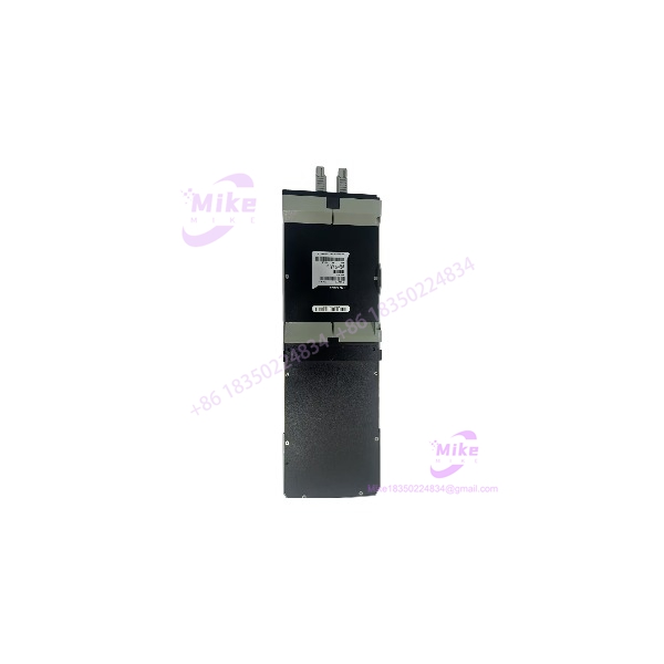
FBM09
Key Technical Specifications
- Manufacturer: Foxboro / Invensys
- System: I/A Series DCS
- Model:
- Product Type: Contact/DC Input/Output Interface Module
- Digital Inputs: 8 independent channels
- Digital Outputs: 8 independent channels
- Input Configuration: Contact sensing or DC voltage monitoring
- Output Configuration: External-source DC switching or internal-source DC switching
- Input Filter: 4, 8, 16, or 32 ms, configurable
- Communication: Redundant I/A Series Fieldbus
- Supply Voltage: 26–42 VDC, redundant
- Power Consumption: 8 W maximum, main module only
- Power Consumption with FBM14: 11 W maximum
- Heat Dissipation: 11 W maximum, main module only
- Heat Dissipation with FBM14: 18 W maximum
- Input/Output Isolation Test: 1250 VAC for one minute under specified test conditions
- Operating Temperature: 0 to 60°C
- Storage Temperature: -40 to +70°C
- Relative Humidity: 5–95%, noncondensing
- Operating Altitude: -300 to +3,000 m
- Storage Altitude: -300 to +12,000 m
- Approximate Mass: 1 kg
- Mounting: I/A Series 1×8 mounting structure, industrial/field enclosures depending on adapter configuration
- Termination: 32 screw-clamp terminals or 34-pin plug-connector arrangements depending on termination assembly
The manufacturer specification states that the eight inputs are isolated in pairs. For hazardous voltages above 60 VDC, both channels in a channel pair must be used with hazardous voltage; hazardous and nonhazardous voltages must not be mixed within the same pair.
Input Specifications
Contact-sensing configuration:
- Open-circuit voltage: 24 VDC ±10%
- Short-circuit current: 2.5 mA maximum
- ON-state resistance: 1 kΩ maximum
- OFF-state resistance: 100 kΩ minimum
DC voltage-monitoring configuration:
- ON-state voltage: 15–130 VDC
- OFF-state voltage: 0–5 VDC
- Typical input current: 2.2 mA at 5–130 VDC
- ON-state source resistance: 1 kΩ maximum at 15 VDC
- OFF-state source resistance: 100 kΩ minimum at 130 VDC
For CSA/FM-rated versions carrying CM-series part numbers, the specification limits the input voltage to less than 60 VDC. Verify the exact certification and part-number suffix before applying higher field voltage.
Output Specifications
External-source output switching:
- Maximum applied voltage: 60 VDC
- Maximum load current: 0.5 A
- Typical ON-state voltage drop: 0.5 V at 0.5 A
- Typical current limit: 0.75 A
- Typical OFF-state leakage: less than 100 µA
- Maximum OFF-state leakage: 1 mA
- Shorted-load duration: indefinite, subject to the specified duty-cycle current limitation
Inductive loads require a customer-supplied protective diode across the load. The diode must be rated for the expected load current and have a voltage rating greater than 1.3 times the supply voltage.
Internal-source output switching:
- No-load output voltage: 11 VDC ±2 VDC
- Nominal source resistance: 660 Ω
- Shorted-output ON-state duration: indefinite
- Typical OFF-state leakage: less than 100 µA
- Maximum OFF-state leakage: 0.5 mA
Global Sourcing & Live-Test SOP
1. Inbound Verification
For a used or surplus , identify the electrical configuration before applying power.
- Confirm the module marking and complete part number.
- Record the revision and serial/date information.
- Determine whether the installation uses FBM09A, FBM09B, FBM09C, or FBM09D.
- Photograph the termination assembly.
- Inspect connectors and terminals for corrosion or mechanical damage.
- Check the PCB for contamination, overheating, or previous repairs.
- Verify the termination assembly against the customer’s existing installation.
- Trace the field wiring before approving a replacement.
The suffix matters because the source configuration and input mode change with the suffix.
2. Live Simulation
A proper functional test should use an I/A Series-compatible Fieldbus environment.
Recommended checks:
- Verify redundant 26–42 VDC supply.
- Establish Fieldbus communication.
- Confirm module initialization.
- Test all eight input channels.
- Simulate contact inputs where applicable.
- Simulate DC voltage inputs where applicable.
- Verify the configured input filter.
- Test all eight outputs individually.
- Measure output voltage and load current.
- Verify external-source or internal-source operation according to the module configuration.
- Check channel status indication.
A generic power-on test is not sufficient to establish that an is fully functional.
3. Diagnostics
Use calibrated instrumentation for:
- Supply-voltage verification.
- Input ON/OFF threshold verification.
- Output-current measurement.
- Output voltage-drop measurement.
- Fieldbus communication verification.
- Channel isolation checks where practical.
- Input-filter response verification.
- Intermittent connector testing.
For output testing, use controlled resistive loads or suitable electronic loads rather than connecting unknown field actuators directly to a surplus module.
4. Final Preparation
Before shipment:
- Clean the module with an electronics-safe process.
- Protect the Fieldbus and termination connectors against ESD.
- Record the exact suffix and revision.
- Record test status and measured values when testing has actually been performed.
- Package with mechanical and ESD protection.
- Clearly identify new, used, refurbished, or untested condition.
Do not represent surplus hardware as factory-tested or factory-sealed without documentary evidence.
Field Engineer’s Pitfall Guide
❗ Do not treat every as the same wiring configuration:
The family includes A/B/C/D configurations. Some use voltage monitoring, some use contact sensing, and the output-source arrangement also changes. Confirm the exact suffix before wiring the replacement.
❗ Respect the input-pair isolation arrangement:
The inputs are isolated in pairs. When hazardous voltage is involved, the manufacturer requires both channels in the pair to be used with hazardous voltage; mixing hazardous and nonhazardous circuits within one pair is prohibited.
❗ Protect inductive output loads:
When an external-source output drives an inductive load, the Foxboro specification requires a protective diode across the load. Omitting the suppression component can expose the output switch to damaging transients.
Intent-Driven FAQ
What is the Foxboro ?
The is an I/A Series Contact/DC Input/Output Interface Module with eight digital inputs and eight digital outputs.
How many I/O points does provide?
It provides 8 digital inputs and 8 digital outputs, for 16 discrete field channels in total.
Can the inputs accept both contacts and DC voltage?
Yes, but the eight input channels are configured collectively for either contact sensing or DC voltage monitoring. The configuration should match the field termination arrangement.
What is the maximum DC voltage for the voltage-monitoring input?
The general specification gives an ON-state range of 15–130 VDC. However, CSA/FM-rated CM-series versions have a lower limit of less than 60 VDC, so the complete part number and certification must be checked first.
What is the maximum output current?
For the external-source switching configuration, the specified maximum load current is 0.5 A per channel. The typical current limit is approximately 0.75 A.
Can control inductive loads?
Yes, within the specified output limits, but an external protective diode is required across an inductive load when using the external-source output configuration.
Can FBM14 be connected to ?
Yes. is the expandable main module and can support one FBM14 expansion module. The communicates through the supporting rather than independently connecting to the Fieldbus.





