


Description
Foxboro FBM07 | 16-Channel Contact/DC Input Module
Product Introduction
For legacy DCS installations, a digital input module is not interchangeable simply because the terminal count looks right. Foxboro FBM07 is a dedicated I/A Series interface for contact and DC discrete signals, with sixteen independent input channels and configurable signal filtering.
The original Foxboro specification identifies FBM07 as the Contact/DC Input Interface Module, while FBM12 is the corresponding expansion module. Schneider Electric continues to list the FBM07/FBM12 documentation within the mature I/A Series Fieldbus Module portfolio.
The FBM07 architecture supports two principal field-input configurations. FBM07A is associated with voltage-monitoring applications, while FBM07B is used for contact-sensing applications. Both are based on the same 16-channel FBM07 hardware family, but the field signal characteristics and termination configuration must match the installed application.
That distinction is important during replacement. A procurement team should verify the exact suffix, termination assembly, field voltage, and DCS configuration rather than treating every listing as electrically identical.
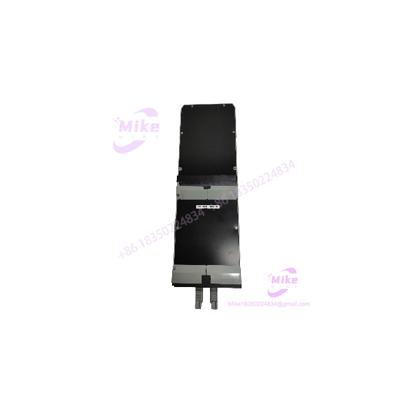
FBM07
Key Technical Specifications
- Manufacturer: Foxboro
- System: I/A Series
- Model:
- Product Type: Contact/DC Input Interface Module
- Number of Inputs: 16 independent digital inputs
- Input Isolation: Inputs isolated from earth/ground and from other channel pairs
- Input Filter: Configurable 4, 8, 16, or 32 ms
- Communication: Redundant I/A Series Fieldbus
- Module Supply: 26–42 VDC redundant input range
- Maximum Power Consumption: 7 W, main module
- Maximum Heat Dissipation: 12 W, main module
- Operating Temperature: 0 to 60°C
- Storage Temperature: -40 to +70°C
- Relative Humidity: 5–95%, noncondensing
- Altitude: -300 to +3,000 m operating
- Approximate Mass: 1 kg
- Status Indicators: Red/green operational LEDs plus individual channel-status indication through the termination assembly
FBM07A Voltage-Monitoring Configuration
The voltage-monitoring configuration supports:
- ON-state voltage: 15–130 VDC
- OFF-state voltage: 0–5 VDC
- Typical input current: approximately 2.2 mA at 5–130 VDC
- ON-state source resistance: 1 kΩ maximum
- OFF-state source resistance: 100 kΩ minimum
For CSA/FM-rated versions with CM-series part numbers, the documented input voltage limitation can be lower than the general 130 VDC range. Verify the exact certification suffix before applying field voltage.
FBM07B Contact-Sensor Configuration
The contact-sensing configuration is intended for dry-contact or equivalent switching devices:
- Contact state: Open = OFF; closed = ON
- Open-circuit voltage: 24 VDC ±10%
- Short-circuit current: 2.5 mA maximum
- ON-state resistance: 1 kΩ maximum
- OFF-state resistance: 100 kΩ minimum
The exact field termination arrangement determines whether the installed is being used in the contact-sense or voltage-monitoring configuration.
Global Sourcing & Live-Test SOP
1. Inbound Verification
Before energizing a surplus or refurbished :
- Confirm the module marking is .
- Record the complete part number and revision.
- Determine whether the installation requires FBM07A or FBM07B functionality.
- Photograph the module and termination assembly.
- Inspect connectors for bent, recessed, oxidized, or contaminated contacts.
- Check the PCB for corrosion, overheating, damaged components, or previous repair work.
- Verify serial/date information for procurement traceability.
- Compare the termination hardware with the customer’s existing installation.
The termination assembly should be treated as part of the electrical identification process, not merely as a mechanical accessory.
2. Live Simulation
A proper functional test should use an I/A Series-compatible test environment.
Recommended checks include:
- Verify redundant module power.
- Establish I/A Series Fieldbus communication.
- Confirm module initialization.
- Apply controlled DC input signals to individual channels.
- Test ON/OFF transitions.
- Verify configured input filtering.
- Check every channel independently.
- Confirm channel-status indication.
- Test the appropriate voltage range for the actual FBM07A/FBM07B configuration.
- Verify that the DCS receives the expected discrete states.
For contact-sense testing, use a controlled contact simulator rather than randomly shorting field terminals.
3. Diagnostics
Acceptance testing should include:
- Fieldbus communication verification.
- Input-channel state verification.
- Filter-time verification.
- Channel isolation checks where practical.
- Supply-voltage measurement.
- Current-consumption measurement.
- Status LED inspection.
- Intermittent-contact testing.
- Extended thermal operation for critical applications.
A calibrated multimeter is appropriate for verifying DC input voltage and supply conditions, while a controlled switching source can verify digital-state transitions.
4. Final Preparation
Before shipment:
- Clean the module using an electronics-safe process.
- Protect connectors against ESD and contamination.
- Record model, revision, serial information, and test status.
- Package in ESD-safe material.
- Protect the termination interface from mechanical impact.
- Clearly identify new, used, refurbished, or untested condition.
Do not claim factory testing or OEM-sealed condition without supporting documentation.
Field Engineer’s Pitfall Guide
❗ Do not confuse with FBM08:
is the Contact/DC Input module, while FBM08 is the 120 VAC Input module. The two belong to the same legacy I/A Series family but have substantially different field-input requirements.
❗ Verify FBM07A versus FBM07B:
The input electronics support different field-use configurations. FBM07A is associated with voltage monitoring, while FBM07B is associated with contact sensing. Installing the wrong termination arrangement can create an apparently functional module with incorrect field interpretation.
❗ Do not overlook the input filter setting:
The provides selectable 4, 8, 16, or 32 ms filtering. If the original application uses pulse counting, sequence-of-events, or fast discrete transitions, changing the filter configuration can affect the observed signal behavior. The I/A Series documentation specifically identifies these application modes and filter settings.
Intent-Driven FAQ
What is the Foxboro ?
The is a Foxboro I/A Series 100 Contact/DC Input Interface Module providing 16 independent digital input channels.
How many inputs does have?
It provides 16 independent digital input channels. The channels are designed for contact/DC input applications and have electrical isolation characteristics suitable for industrial DCS installations.
What is the difference between and ?
is associated with voltage-monitoring inputs, while is associated with contact-sensor inputs. The appropriate termination and field wiring must match the application.
Can accept 24 VDC inputs?
Yes, but the exact connection depends on the configuration. uses a 24 VDC ±10% open-circuit contact-sensing supply, while the voltage-monitoring configuration supports a substantially wider DC voltage range.
Is an analog input module?
No. is a discrete/digital input module. Foxboro’s I/A Series family uses FBM01 for 0–20 mA analog input, FBM02 for thermocouple/mV input, and FBM03 for RTD input.
Is still a current-generation module?
belongs to the mature/legacy I/A Series 100 hardware family. Schneider Electric still maintains the historical product documentation, while newer I/A Series architectures use newer-generation FBMs.
What should be checked before buying a replacement ?
Confirm the complete part number, / configuration, termination assembly, field voltage, connector arrangement, revision, and existing I/A Series system configuration. For a used unit, obtain clear photographs of both the module label and termination interface whenever possible.





