


Description
Foxboro 871EC-SP0 | Electrodeless Conductivity Sensor Core Category
Dynamic Product Introduction
Process fluid measurement failures in aggressive chemical streams usually start with surface scaling on standard contacting conductivity probes. When heavy mineral buildup or corrosive acids coat traditional metallic electrodes, reading drift destroys chemical concentration loops. The Foxboro 871EC-SP0 electrodeless conductivity sensor bypasses this limitation by using magnetic induction through a rugged PEEK body—completely eliminating direct fluid contact with the sensing elements.
Unlike fragile glass or platinum sensors, this toroidal design thrives in harsh pickling baths, clean-in-place (CIP) loops, and chemical recovery lines. Maintaining precise electrodeless measurement on legacy industrial skids demands exact part matching—making this specific probe essential for avoiding off-spec production batches.
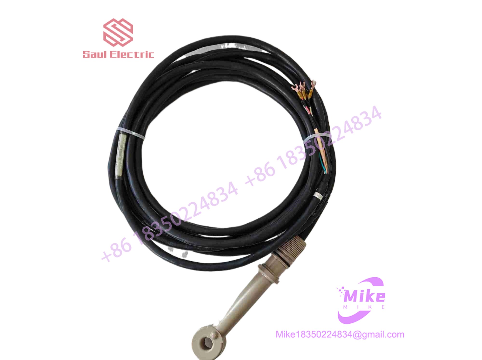
871EC-SP0
Key Technical Specifications
| Parameter | Specification Detail |
| Manufacturer | Foxboro (Schneider Electric) |
| Model Number | 871EC-SP0 |
| Sensor Type | Electrodeless / Toroidal Conductivity Probe |
| Wetted Body Material | PEEK (Polyetheretherketone) for high chemical resistance |
| Process Connection | Standard industrial thread / flange mounting options |
| Temperature Limits | Up to 125^\circ C (257^\circ F) continuous rating |
| Cable Interface | Integral shielded cable for remote transmitter connection |
| Operating Environment | Industrial process piping and heavy chemical plants |
Global Sourcing & Live-Test SOP (Transparency Core)
Acquiring secondary-market industrial analytical sensors requires strict verification to ensure zero internal coil damage, micro-cracks in the PEEK housing, or signal attenuation before installation. Our qualification workflow covers:
- Inbound Verification: Incoming sensors undergo microscopic inspection along the PEEK wetted body to check for chemical etching, thermal warping, or mechanical impact marks on the toroid housing. Original OEM laser tags are cross-referenced against historical traceability records.
- Live Simulation: We mount the probe into a dedicated fluid test fixture calibrated to mimic active process pipe conditions.
- Diagnostics: Engineers run multi-point conductivity standard solutions across the sensor, verifying coil inductance, temperature compensation accuracy, and signal linearity using high-precision multimeters and loop calibrators.
- Final Prep: Once testing criteria are met, the sensor body is cleaned, the cable ends are inspected for pin corrosion, and the unit is sealed inside protective packaging prior to dispatch.
The Field Engineer’s Pitfall Guide
❗ Ignoring Temperature Compensation Settings: Failing to properly configure the Pt100/Pt1000 temperature compensation element in the companion transmitter will introduce massive measurement skew as process fluid temperatures fluctuate.
❗ Improper Insertion Depth: Mounting the sensor too flush against a pipe wall can restrict fluid flow through the toroidal bore, causing artificially low or unstable conductivity readings. Ensure the flow path through the center of the sensor is completely unobstructed.
❗ Ground Loop Interference: I’ve seen technicians leave the shield wire floating on long cable runs, injecting massive electrical noise from nearby variable frequency drives (VFDs) straight into the measurement loop. Always terminate the shield correctly at the transmitter ground terminal.
Intent-Driven FAQ
Can the 871EC-SP0 sensor be connected directly to a PLC, or does it require a transmitter?
It requires a compatible Foxboro electrochemical transmitter (such as the 871EC or 870IT series) to process the raw induced signal and convert it into a standard 4-20mA or digital output loop for the PLC.
What causes electrodeless sensors to fail in chemical service?
While the PEEK body offers exceptional chemical resistance, extreme thermal shock, physical abrasion from heavy slurries, or aggressive solvents exceeding the polymer’s rating can eventually cause micro-cracks and fluid ingress into the internal coils.
How do I test if my conductivity drift is caused by the sensor or the analyzer?
Disconnect the sensor and attach a certified resistor substitution box or Foxboro test plug to the transmitter inputs. If the transmitter reads the correct simulated value, the issue lies with the probe or process fouling.
Is the cable length on this sensor field-modifiable?
No. Splicing or shortening the integral cable changes the total loop capacitance and resistance, which will invalidate factory calibration. Always order the correct cable length for your run.
What warranty is provided with this surplus industrial sensor?
We back this unit with a comprehensive one-year replacement warranty, covering structural integrity and electrical signal calibration under normal industrial operating conditions.





