

Description
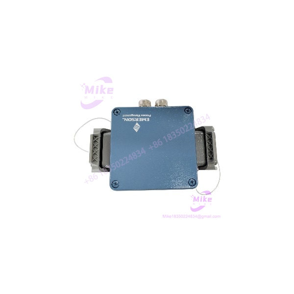
EPRO MMS3125/022-020 | Dual-Channel Vibration Transmitter
Product Introduction
The EPRO MMS3125/022-020 is a two-channel transmitter for continuous monitoring of absolute bearing vibration on rotating machinery. It belongs to the revised MMS 3000 transmitter family and is designed around piezoelectric/IPC vibration sensors rather than the electrodynamic sensor arrangement used by earlier MMS transmitter variants.
That distinction matters during a field replacement. The MMS3125/022-020 accepts compatible piezoelectric vibration-sensor signals, processes each channel independently, and produces 0/4–20 mA signals suitable for PLC, DCS, machinery-protection, or supervisory monitoring systems. Its measurement bandwidth extends to 12 kHz, while integrated sensor/electronics supervision provides additional fault detection.
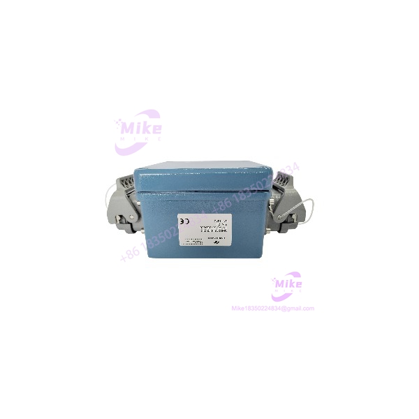
MMS3125/022-020
Key Technical Specifications
- Model: EPRO MMS3125/022-020
- Inventory designation: MMS3125022-020
- Product family: MMS 3125
- System: MMS 3000
- Function: Dual-channel absolute bearing-vibration measurement and transmission
- Measurement channels: 2
- Sensor technology: Piezoelectric / IPC absolute-vibration sensors
- Supported sensor configuration: The MMS 3125 family documentation identifies IPC sensors including 100 mV/g and 100 mV/in/s variants, with configuration depending on the ordered hardware option.
- Measurement frequency: Up to 12 kHz
- Analog current outputs: 2 × 0/4–20 mA
- Function outputs: Up to 5 configurable outputs
- Output options: Depending on configuration, function outputs can use optocoupler, relay, or PhotoMOS arrangements.
- Communication options: RS-232, RS-485, or PROFIBUS DP depending on hardware configuration.
- Configuration software: MMS 3910W, supplied as part of the MMS ParaKit environment.
- Power: Two redundant 24 VDC supply inputs
- Diagnostics: Electronic module supervision and sensor supervision
- Microcontroller: Integrated
- Installation: Direct mounting at the monitored machine
- Application standard: Designed with reference to VDI 2059 and API 670 requirements.
- Typical machinery: Turbines, compressors, fans, pumps, gearboxes, and other rotating machinery.
- Machine types: Applications include both plain-bearing and rolling-bearing machinery.
- Approximate enclosure dimensions: 160 × 160 × 120 mm
- Approximate weight: 0.8 kg
The MMS3125 family is hardware-configurable. The published documentation specifically states that sensor input, communication, current-output isolation, function outputs, and display options can vary by order configuration. Therefore, the suffix 022-020 should be matched against the complete unit configuration, not treated as a generic MMS 3125 card.
Application Scenarios & Pain Points
Turbine Bearing-Vibration Monitoring
For turbine machinery, bearing vibration is a core protection and condition-monitoring parameter. The two channels allow two measurement points to be processed locally before the signals are sent onward to the plant control or monitoring system.
Compressor and Pump Monitoring
The MMS3125/022-020 is suitable for continuous absolute-vibration monitoring on compressors, pumps, fans, and similar rotating equipment. The 0/4–20 mA outputs make integration with conventional analog-input systems straightforward when the receiving system is correctly scaled.
High-Frequency Machinery Diagnostics
With a measurement range extending to 12 kHz, the family provides substantially more bandwidth than a simple low-frequency process transmitter. This can matter when the vibration-monitoring application requires higher-frequency information from piezoelectric sensors.
Distributed Monitoring
The MMS 3000 architecture can be used in larger plants with PLCs and host computers as well as smaller installations with fewer measurement points. That makes the transmitter useful for decentralized monitoring where mounting the signal-conditioning hardware near the machine simplifies field wiring.
Legacy Transmitter Replacement
This is where engineers need to slow down. A replacement transmitter may have the same physical dimensions and still be electrically wrong because the original system uses a different sensor technology, signal sensitivity, output configuration, or communication option.
QA & Live Testing SOP
For an incoming , acceptance testing should reproduce the actual sensor-to-DCS signal path.
- Visual inspection: Check the enclosure, terminals, connector pins, mounting hardware, PCB condition, and evidence of corrosion or unauthorized rework.
- Power test: Apply a controlled 24 VDC supply and verify stable startup.
- Redundant supply test: Where practical, verify both supply inputs independently.
- Sensor-interface verification: Use an appropriate calibrated piezoelectric/IPC vibration simulator rather than applying an arbitrary voltage signal.
- Channel 1 test: Inject a known vibration signal and verify the corresponding output.
- Channel 2 test: Repeat independently; never assume both channels are healthy because Channel 1 passes.
- Frequency sweep: Exercise representative low-, mid-, and high-frequency points within the configured measurement range.
- Current-output test: Verify the corresponding 0/4–20 mA response and confirm that the DCS/PLC scaling agrees with the transmitter configuration.
- Alarm/output test: Exercise each configured function output and confirm the expected state transitions.
- Sensor-fault simulation: Where the test equipment permits, simulate an input fault and verify sensor-supervision behavior.
- Communication test: Verify the installed RS-232, RS-485, or PROFIBUS option rather than assuming every /022-020 has identical communication hardware.
- Configuration backup: Record the MMS 3910W configuration before commissioning or returning a replacement to service.
- ESD packaging: Use ESD-safe packaging and protect the field terminals during shipment.
A proper acceptance test should follow the complete chain:
Sensor → /022-020 → signal processing → current output/function output → PLC/DCS input.
Power-up alone proves very little.
Field Engineer’s Pitfall Guide
❗ Do not substitute MMS3120/022-000 without checking the sensor technology. The /022-020 is specifically associated with piezoelectric/IPC vibration sensors, while the MMS3120 family uses a different sensor architecture. A connector match does not establish measurement compatibility.
❗ Verify the complete hardware option set. MMS 3125 transmitters were available with different communication interfaces, output isolation arrangements, function outputs, and display options. Do not assume every unit carries RS-485, PROFIBUS, or the same relay/output hardware.
❗ Check sensor sensitivity before commissioning. IPC sensors can have different sensitivities, including documented 100 mV/g and 100 mV/in/s configurations. The transmitter configuration must correspond to the installed sensor.
❗ Do not overlook software configuration. The MMS 3125 family uses MMS 3910W for configuration. Measurement range, frequency filtering, characteristic variables, current scaling, alarm limits, hysteresis, response delay, and output behavior can all depend on configuration.
❗ Verify the hazardous-area architecture separately. The family can be configured for sensor operation associated with explosive-area applications, but the exact installation must be checked against the certified sensor/barrier/system arrangement. Do not infer hazardous-area approval from the transmitter model alone.
Intent-Driven FAQ
Q: What is the EPRO /022-020?
A: It is a dual-channel bearing-vibration transmitter from the MMS 3000 family, designed to process absolute vibration signals from compatible piezoelectric/IPC sensors.
Q: What type of sensor does /022-020 use?
A: The configuration is associated with piezoelectric/IPC absolute-vibration sensors. The MMS 3125 documentation also identifies IPC sensitivity options such as 100 mV/g and 100 mV/in/s.
Q: How many channels does /022-020 have?
A: Two independent bearing-vibration channels.
Q: What is the frequency range of /022-020?
A: The published product description specifies a measurement frequency range of up to 12 kHz.
Q: What outputs does /022-020 provide?
A: The standard description specifies two 0/4–20 mA current outputs. Depending on the hardware configuration, up to five configurable function outputs are also available.
Q: Does /022-020 use 24 VDC power?
A: Yes. The documented design provides two redundant 24 VDC supply inputs.
Q: Can /022-020 replace an MMS3120?
A: Not automatically. The critical issue is the sensor interface. The /022-020 is intended for piezoelectric/IPC sensor applications, so the installed sensor, signal sensitivity, scaling, and complete transmitter configuration must be compared before substitution.
Q: How is /022-020 configured?
A: The MMS 3125 documentation identifies MMS 3910W configuration software as part of the MMS ParaKit environment. Configuration can include sensor sensitivity, measuring range, filtering, characteristic variables, current calibration, alarm limits, hysteresis, response delay, and output behavior.
Q: What should be verified before purchasing MMS3125022-020?
A: Confirm the exact designation, installed piezoelectric sensor type and sensitivity, required frequency range, 0/4–20 mA scaling, function-output hardware, communication interface, power arrangement, and existing MMS 3000 configuration. For a legacy turbine installation, matching the measurement chain is more important than matching the enclosure dimensions alone.





