Description
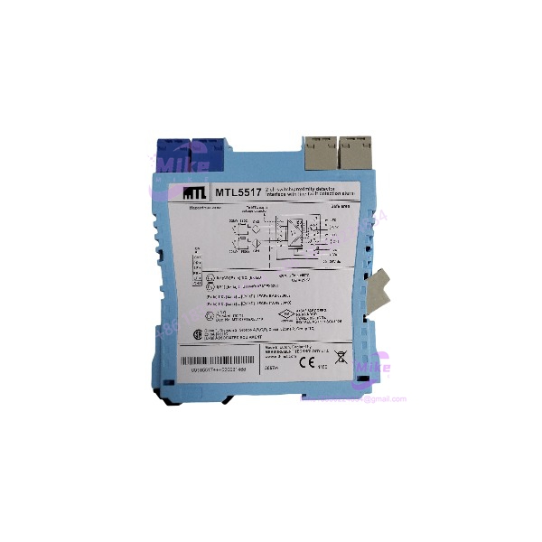
Eaton MTL5517 | 2-Channel Switch / Proximity Detector Interface
Architect’s Product Breakdown
The Eaton MTL5517 operates as a dual-channel intrinsically safe isolating interface designed to link field-level switches or proximity detectors in explosive atmospheres directly with safe-area control logic. Belonging to the widely deployed MTL5500 DIN rail product family, this unit eliminates the requirement for dedicated safety earth wiring by providing complete galvanic isolation between hazardous zones and control room hardware.
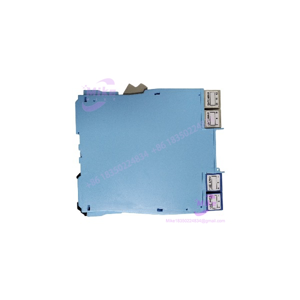
Deploying this hardware requires careful planning regarding cabinet layout and power distribution rails. Because the unit snaps directly onto standard 35 mm DIN rail carriers, thermal management and side-switch configurations must be addressed prior to commissioning. Technicians must verify phase reversal and line fault detection settings via the physical DIP switches on the side housing before sliding the unit into active loops, preventing unexpected signal logic inversions.
MTL5517
Key Technical Specifications
| Parameter | Specification |
| Model Designation | MTL5517 |
| Number of Channels | Two independent channels |
| Supply Voltage | 20 V to 35 V DC |
| Current Consumption | 35 mA typical at 24 V DC |
| Sensor Input | NAMUR proximity detectors or mechanical switches |
| Safe-Area Output | Two single-pole relays (NO) + dedicated LFD changeover relay |
| Contact Rating | 250 V AC, 2A, cos >0.7; 40 V DC, 2A resistive |
| Power Dissipation | 0.84 W at 24 V DC |
| Ambient Operating Temperature | -20°C to +60°C |
| Mounting Style | 35 mm DIN Rail |
Field Engineer’s Pitfall Guide
- WARNING: Unbalanced End-of-Line Resistors. When applying line fault detection with standard mechanical dry contacts rather than NAMUR sensors, failing to install the required series (500 to 1k ohm) and parallel (20k to 25k ohm) balancing resistors will trigger constant fault states. I once spent an entire graveyard shift troubleshooting a spurious trip loop because the installation crew forgot the parallel resistor on a push-button input.
- WARNING: DIN Rail Power Bus Overloads. Ensure your power supply can handle the inrush current when populating large racks with multiple interface modules. Overloading a single power rail segment will cause voltage sags and drop relay outputs across adjacent channels.
- WARNING: Terminal Screw Torque Limits. Do not overtighten the cage-clamp or screw terminals during field wiring; stripped terminal blocks will ruin the module housing and demand a complete hardware swap.
QA & Testing SOP
- Visual & Origin Verification: Inspect the outer polyamide housing for cracks, verify OEM laser-etched tracking data, and check pin terminals for oxidation.
- Power-Rail Bench Test: Mount the module onto a live DIN rail test rig powered by a regulated 24V DC supply to confirm stable green power LED illumination.
- Input Simulation & Relay Handshake: Inject test currents using a process calibrator to simulate open-circuit, closed-switch, and NAMUR sensor states, verifying correct relay actuation.
- Line Fault Verification: Induce short and open faults on the input terminals to validate proper LFD red LED activation and line fault relay response.
- Packaging: Seal in an anti-static moisture-barrier bag and pack with dense anti-static foam cushioning.
Technical FAQ
Can I hot-swap this isolator model while the cabinet power is active? DIN-rail mounted units like the MTL5517 generally require isolating power before disconnecting terminal blocks, unless specific pluggable connector variants and safety protocols allow live maintenance.
How do I configure line fault detection on this specific model? Line fault detection and phase reversal settings are managed entirely via physical slide switches located on the side housing of the module prior to installation.
What types of field switches are compatible with the input channels?The module accepts standard NAMUR proximity detectors conforming to EN 60947-5-6 standards as well as conventional mechanical dry contacts equipped with proper balancing resistors.
Does this interface barrier require an external safety earth connection? No. Galvanic isolation eliminates the need for a dedicated safety earth connection in the hazardous area, simplifying field wiring layouts.