


Description
B&R ECPE84-1B | 8-Channel Analog Input Module
Product Introduction
A failed analog input module can create a deceptively difficult plant fault: the transmitter is healthy, the field wiring checks out, yet the PLC sees zero, unstable, or completely implausible process data. B&R ECPE84-1B sits at that exact measurement boundary, accepting analog voltage signals and transferring the converted values into the B&R MULTI control architecture.
The module provides 8 analog input channels, with a documented 0–10 V DC input range and 16-bit conversion resolution. That makes it suitable for voltage-output transmitters and machine instrumentation where the controller needs substantially more measurement granularity than a basic low-resolution analog card can provide.
One procurement warning: do not confuse ECPE84-1B with other B&R PE84 variants. B&R’s official product documentation identifies ECPE84-2 as a different 8-channel MULTI analog input module with 0–25 mA, 15-bit inputs. The suffix matters.
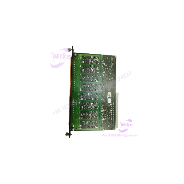
ECPE84-1B
Key Technical Specifications
| Parameter | ECPE84-1B Specification |
|---|---|
| Manufacturer | B&R Industrial Automation |
| Model | ECPE84-1B |
| Series | MULTI |
| Module Type | Analog Input |
| Number of Inputs | 8 channels |
| Input Signal | 0–10 V DC |
| Resolution | 16 bit |
| Input Architecture | Isolated analog inputs |
| Input Impedance | High-impedance input stage |
| Conversion Accuracy | ±0.1% of full scale |
| Operating Temperature | -20°C to +60°C |
| Storage Temperature | -40°C to +85°C |
| Relative Humidity | 5–95% non-condensing |
| System Connection | MULTI backplane interface |
The listed specifications above come from available technical documentation for ECPE84-1B. Because this is legacy hardware, verify revision-specific electrical characteristics against the physical module before making a production-critical substitution.
Application Scenarios & Pain Points
Process Instrumentation
is well suited to systems where field instruments produce voltage outputs such as 0–10 V.
Typical signals include:
- Pressure transmitter outputs
- Position feedback
- Level measurement
- Flow instrumentation
- Temperature controllers with voltage output
- Speed/reference signals
- Machine position sensors
The important distinction is signal type. A 0–10 V transmitter cannot simply be wired into a current-input variant and expected to produce correct scaling.
With vs. Without the Correct Input Module
Eight voltage signals enter the B&R MULTI system through dedicated analog channels, with 16-bit conversion providing fine digital measurement granularity.
Without the correct module:
The engineering team may spend hours checking sensors, cables, grounding, and PLC logic when the actual problem is simply an incompatible analog input range.
That happens more often than it should.
Legacy Machine Repair
A production machine running an older B&R MULTI architecture may not justify a complete controls retrofit because one analog card has failed.
Replacing the matching module can preserve the existing I/O architecture, field wiring, application logic, and scaling configuration—assuming the rest of the system remains serviceable.
Closed-Loop Control
For pressure, flow, position, or speed control, analog feedback quality directly affects the controller’s process value. A high-resolution input module gives the PLC more measurement granularity for scaling and control calculations.
That does not mean every application automatically achieves 16-bit system accuracy. Sensor accuracy, wiring noise, reference voltage, grounding, and signal conditioning still determine the actual field measurement quality.
EMI and Ground-Loop Troubleshooting
Analog voltage signals are susceptible to electrical noise. When a reading oscillates despite a healthy transmitter, check cable routing, shield termination, grounding, and nearby VFD switching before condemning the .
A multimeter reading that looks stable at the transmitter does not necessarily mean the PLC sees a clean signal.
QA & Live Testing SOP
For a legacy analog module, visual inspection alone is not sufficient.
1. OEM Identity Check
- Confirm B&R identification.
- Verify the complete part number.
- Record hardware/revision markings.
- Compare connector and housing configuration with the customer’s existing module.
2. Physical Inspection
Inspect:
- Backplane connector
- Terminal/interface connectors
- PCB condition
- Housing and mounting points
- Evidence of overheating or corrosion
- Damaged or contaminated contacts
3. Controlled Power-Up
Install the module into a compatible B&R MULTI test rack.
Check:
- Startup behavior
- Status indicators
- Rack recognition
- Abnormal current draw
- Module diagnostic status
4. Analog Input Test
A proper test should use calibrated voltage sources rather than simply checking continuity.
For each channel, verify representative points such as:
- 0 V
- 2.5 V
- 5.0 V
- 7.5 V
- 10.0 V
Confirm that the corresponding digital values are stable and scale correctly in the controller.
5. Channel-to-Channel Verification
Because this module has eight inputs, test all eight channels independently.
Do not test Channel 1 and assume Channels 2–8 are healthy.
6. ESD-Safe Packaging
After testing:
- Place the electronics in ESD-safe packaging.
- Protect the backplane connector.
- Prevent terminal damage during shipment.
- Use sufficient cushioning for international transport.
Engineer rule: A module that powers up is not necessarily a good analog module. The meaningful test is whether every input channel converts known voltage values correctly.
Field Engineer’s Pitfall Guide
❗ Do not confuse with ECPE84-2
This is probably the most important purchasing warning.
B&R’s official documentation lists ECPE84-2 as an 8-channel 0–25 mA, 15-bit analog input module. That is fundamentally different from the documented 0–10 V, 16-bit configuration.
The modules may look similar enough to cause an expensive mistake.
❗ Verify the transmitter’s output type
Before installation, determine whether the field instrument provides:
- 0–10 V
- ±10 V
- 4–20 mA
- 0–20 mA
- Another proprietary signal
Do not connect a current-output transmitter to the simply because the terminal arrangement fits.
❗ Check scaling in the PLC application
Even when the electrical signal is correct, the PLC engineering value can still be wrong.
For example, a 0–10 V signal representing 0–100 bar needs the correct engineering-unit scaling in software. Replacing the hardware without checking the existing scaling can create a perfectly stable—and completely wrong—process value.
❗ Watch analog cable routing
Keep low-level analog wiring away from VFD motor cables, contactors, switching power supplies, and other high-noise conductors.
If the process value jumps when a drive starts, investigate the installation before replacing the input card.
Intent-Driven FAQ
What is B&R ?
B&R is an 8-channel MULTI analog input module designed for 0–10 V DC signals. Available specifications identify 16-bit resolution for the module.
How many analog inputs does have?
It provides 8 analog input channels. Each channel is intended for voltage-based analog measurement.
Is a 0–10 V input module?
Yes. Available technical information specifies a 0–10 V DC input range.
Is the same as ECPE84-2?
No. Do not treat them as interchangeable. B&R identifies ECPE84-2 as an 8-input, 0–25 mA, 15-bit MULTI analog input module, while available specifications identify 0–10 V, 16-bit operation.
What resolution does provide?
The available technical specification lists 16-bit resolution. That provides substantially finer digital quantization than a lower-resolution analog input card, although total measurement accuracy also depends on the sensor, wiring, noise, and signal conditioning.
Can I use for a 4–20 mA transmitter?
Not directly as a standard 4–20 mA input. is documented as a 0–10 V voltage-input module. A current-output transmitter requires an appropriate current-input module or a properly engineered signal-conversion interface.





