


Description
Bently Nevada 149992-01 | 3500/33 16-Channel Relay Output Module Core Category
Dynamic Product Introduction
Managing critical safety shutdowns and alarm signaling across complex industrial machinery protection frameworks requires high-density, reliable switching hardware. The Bently Nevada 149992-01 operates as a spare 16-channel relay output module engineered to integrate directly into the 3500/33 series rack architecture. Unlike standard mechanical relays that can suffer from contact wear or sluggish response times under heavy continuous switching operations, this high-density module provides dependable, independently programmable outputs designed to link machinery events directly with plant safety instrumented systems.
Moving beyond legacy discrete relay boards, this 16-channel platform allows engineers to configure complex voting logic and alarm drive combinations across multiple system channels. Field maintenance records indicate that dropping in a verified replacement relay module instantly resolves output switching faults, restores proper alarm transmission to control rooms, and ensures reliable machine trip protection.
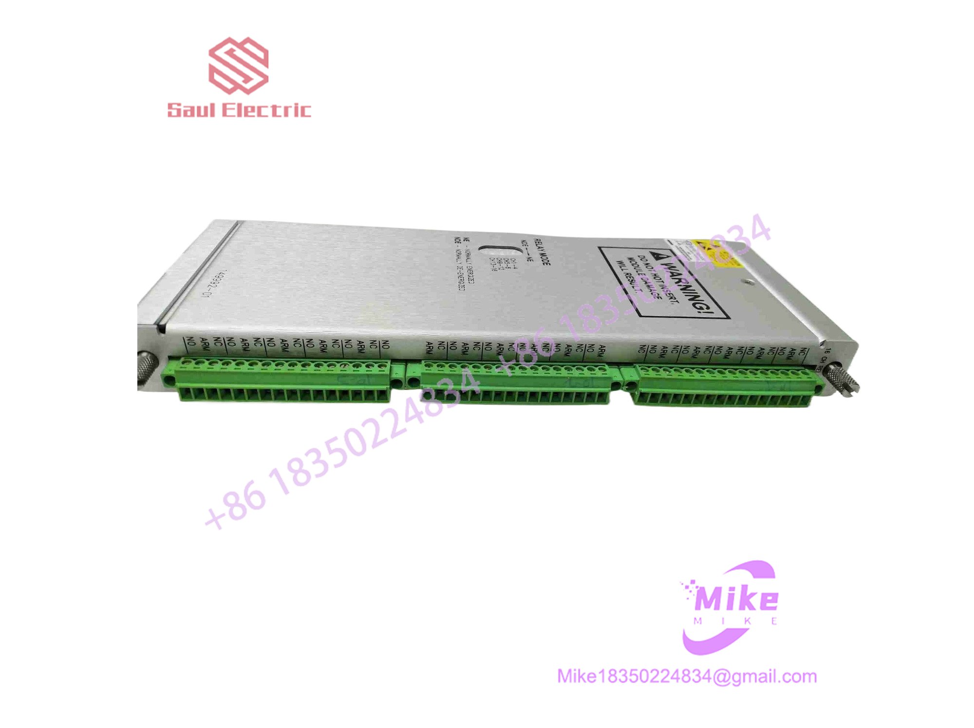
149992-01
Key Technical Specifications
- Module Architecture: 16-Channel Relay Output Module (3500/33 Series)
- System Compatibility: Bently Nevada 3500 Series Machinery Protection Racks
- Channel Capacity: 16 independently programmable relay outputs
- Power Consumption: ~5.8 Watts typical
- Operating Voltage: 24V DC internal logic supply
- Max Switched Current: 6A
- Max Switched Power: 160W DC / 1500VA AC
- Operating Temperature Range: -30^\circC to +65^\circC (-22^\circF to +149^\circF)
- Weight: Main module ~0.7 kg (1.6 lbs); I/O module ~0.4 kg (1.0 lb)
Global Sourcing & Live-Test SOP (Transparency Core)
Deploying replacement relay output modules on active safety-instrumented protection racks demands an uncompromising verification protocol to guarantee contact integrity and switching reliability.
- Inbound Verification: Incoming modules are audited against original Bently Nevada manufacturing specifications. Terminal blocks, relay contacts, LED indicators, and backplane connector pins are inspected under optical magnification for pin pitting, corrosion, or thermal stress.
- Live Simulation: The relay module is mounted onto a dedicated 3500 test backplane powered by a regulated 24V DC supply and paired with active monitor simulation cards.
- Diagnostics: Technicians execute full-channel switching sweeps, verifying relay closure response times, voting logic execution accuracy, contact resistance stability, and thermal endurance across a 24-hour burn-in soak cycle.
- Final Prep: Once electrical logs clear baseline standards, terminal blocks are cleaned, protective covers are attached, and the module is sealed inside an anti-static moisture-barrier shield.
The Field Engineer’s Pitfall Guide
❗ Hot-Wiring Field Output Circuits Under Power: Tightening terminal screws or landing external high-voltage control lines onto the rear module block while the system is energized risks accidental short circuits or unintended machinery trip commands. (I’ve seen plants experience accidental unit shutdowns because technicians skipped isolation steps.) Always drop local power before servicing wiring.
❗ Exceeding Relay Contact Current and Voltage Ratings: Forcing heavy inductive loads (such as large solenoid valves or direct motor starters) beyond the module’s maximum switched power limits (160W DC / 1500VA AC) will weld internal relay contacts shut. Always use intermediate interposing relays for heavy loads.
❗ Ignoring Programmable Voting Logic Mismatches: Installing a replacement relay module without verifying that its software-configured voting logic matches the plant safety matrix can lead to missed trips or false alarms during an upset condition. Always audit configuration parameters via 3500 software.
Intent-Driven FAQ
Will swapping this 149992-01 relay module require reprogramming the 3500 rack?
Because relay output configuration and voting logic parameters are stored within the rack’s system software memory, a direct hardware swap typically retains operational programming, though verifying output channel mapping is recommended.
Can this relay output module be replaced while the turbomachinery is running?
Hot-swapping output modules on an active protection rack must be handled with extreme care. Depending on rack configuration and whether the relays are tied to live shutdown circuits, pulling the module can affect safety interlocks. Coordination with operations and adherence to bypass procedures are mandatory.
What causes a specific relay channel to fail to trigger during an alarm?
A non-responding relay channel typically points to a blown internal fuse, a loose terminal screw on the output block, an incorrect software voting logic assignment, or physical contact wear from an overloaded circuit. Checking continuity and software status isolates the fault.
Is the 149992-01 compatible with failsafe and low-current configuration variants?
The 149992-01 is the standard 16-channel relay output module configuration. Bently Nevada also offers specific variants (such as the -02 failsafe or -03 low-current versions) for specialized application requirements.
What kind of warranty accompanies surplus or refurbished units?
Reputable industrial suppliers typically back tested surplus or refurbished Bently Nevada hardware with a standard 1-to-2 year replacement warranty, supported by a bench test report confirming relay contact health.





