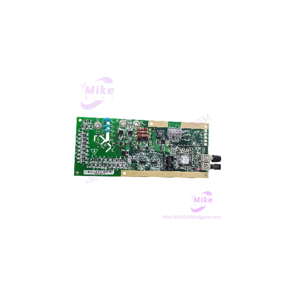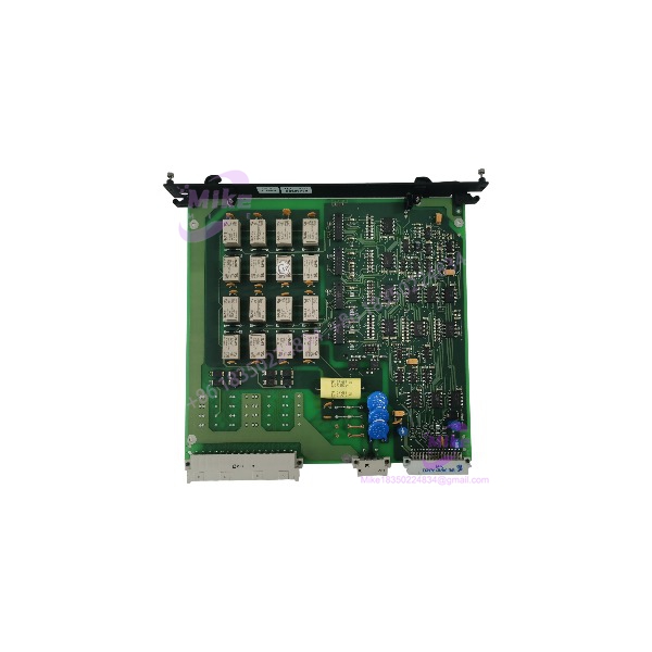
Description
ALSTOM LC105A-1 | 16-Channel Relay Output Board
Product Introduction
A legacy control-system output card is not a generic relay board. Its value depends on the exact rack, backplane, field wiring, and output configuration it was designed to support.
The ALSTOM LC105A-1 is described by a specialist surplus-parts supplier as a 16-channel relay discrete-output board for the ALSPA P320/T2000 control platform. In that reported role, the card provides switched field signals for control functions within the larger automation system. The model-specific function is supported by reseller documentation, but detailed electrical characteristics and OEM configuration data have not been independently confirmed.
For replacement procurement, verify the complete part number and board revision, then compare the physical assembly against the installed card. Do not assume that a similar ALSTOM board—or even a related LC105 variant—is interchangeable without a documented compatibility reference.
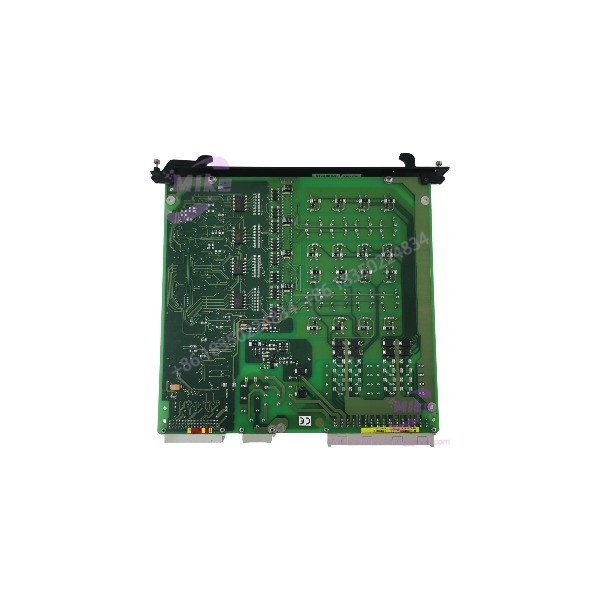
LC105A-1
Key Technical Specifications
The following identification details are based on available third-party product documentation. Treat unverified ratings as open procurement checks.
- Part Number: LC105A-1
- OEM: ALSTOM
- Reported Control Platform: ALSPA P320 / T2000
- Reported Function: Relay discrete-output control
- Reported Channel Count: 16 relay output channels
- Board Format: Eurocard-style plug-in PCB, according to supplier documentation
- Mounting: Reportedly installed in a compatible P320/T2000 subrack
- Output Contact Rating: Not verified
- Maximum Switching Voltage: Not verified
- Maximum Switching Current: Not verified
- Output Contact Arrangement: Not verified
- Isolation Rating: Not verified
- Backplane Pinout: Not verified
- Operating Supply: Not verified
- Operating Temperature: Not verified
- Dimensions: Not verified
Important: Do not use generic reseller claims—such as 220 V, 50 kHz, or broad compatibility—as confirmed LC105A-1 specifications. The available listings do not establish these as reliable OEM ratings for this exact board.
Global Sourcing & Live-Test SOP
1. Inbound Verification
- Photograph the full board, front and rear, before handling or installation.
- Confirm the exact LC105A-1 marking.
- Record all secondary assembly numbers, PCB numbers, and revision markings.
- Inspect the edge connector, backplane contacts, relay components, and solder joints.
- Check for corrosion, contamination, damaged traces, rework, or heat discoloration.
- Compare component placement and connector layout with the original installed card.
- Record the seller’s stated condition and any available test documentation.
2. Platform and Configuration Matching
- Confirm the host system is the documented ALSPA P320/T2000 platform or another platform explicitly listed as compatible by the OEM.
- Compare the card against the machine’s bill of materials and maintenance records.
- Verify the required rack slot and backplane connection.
- Confirm whether the replacement requires matching firmware, configuration data, or system-level setup.
- Do not assume LC105A-1 and LC105A-2 are interchangeable based only on the shared model prefix.
3. Controlled Functional Testing
Testing should be performed by qualified personnel using an approved test fixture or compatible control-system rack.
- Verify supply requirements and connector pinout from reliable documentation before energizing.
- Inspect for shorts or obvious component damage before insertion into the rack.
- Check card recognition and startup diagnostics, where supported.
- Exercise each output channel using a documented test method.
- Verify relay operation and contact state against the correct schematic.
- Do not apply external field voltage until the contact ratings and wiring are confirmed.
- Record channels tested, test conditions, and any failed or intermittent outputs.
4. Extended Run and Diagnostics
Where a suitable test setup is available, conduct an extended run under controlled conditions.
Monitor and record:
- Card recognition and diagnostic status
- Relay actuation consistency
- Output-channel behavior
- Abnormal heating or odor
- Intermittent operation
- Fault indications or resets
A visual inspection or simple power-up is not sufficient evidence that all 16 output channels function correctly.
5. Final Preparation
- Record the serial number, PCB revision, and test date.
- Photograph the card and its connector condition before shipment.
- Preserve original labels and configuration markings.
- Use ESD-safe packaging and mechanical protection for the board.
- Include the functional-test report, if one was performed.
- Clearly disclose any untested channels, limitations, or repair history.
Field Engineer’s Pitfall Guide
❗ Do not assume the relay contact ratings
The reported 16-channel relay-output function does not establish the maximum switching voltage, current, or load type. Verify contact ratings from the applicable technical documentation before connecting field loads.
❗ Confirm the exact control-system platform and revision
The is reported for ALSPA P320/T2000 systems. Do not install it in another ALSTOM platform—or substitute a related LC105 variant—without a documented compatibility check.
❗ A tested board is not automatically a validated system replacement
A bench test may confirm relay operation, but it does not prove correct backplane communication, logic mapping, field wiring, or application behavior. Complete the relevant system-level checks before returning the machine to service.
Intent-Driven FAQ
What is the ALSTOM ?
Third-party product documentation identifies the as a 16-channel relay discrete-output PCB associated with the ALSPA P320/T2000 control platform.
How many output channels does the have?
A specialist supplier describes it as a 16-channel relay-output board. Confirm the channel count and configuration against the actual board and applicable documentation before commissioning.
Is the a standalone controller?
It is described as a plug-in control-system I/O board, not a standalone PLC or complete controller. Its intended operation depends on the compatible host system.
What are the voltage and current ratings?
Model-specific relay contact ratings and supply requirements were not verified. Obtain the applicable OEM documentation before connecting field loads or applying power.
Can the replace an LC105A-2?
Do not assume so. Confirm the hardware revision, electrical characteristics, connector/pinout, and system compatibility using an OEM cross-reference or the original equipment documentation.
Is the obsolete?
It is offered through legacy and surplus-parts channels. Current OEM lifecycle status and service availability for this exact model should be confirmed with ALSTOM’s relevant service organization.
What should I verify before buying a used ?
Request clear front/rear photographs, the complete nameplate or PCB markings, revision details, host-system information, condition disclosures, and channel-level test evidence. Confirm that the card matches the original installed assembly.
Bottom Line for Buyers
The is reported as a 16-channel relay discrete-output board for the ALSPA / control platform. Its exact electrical ratings, pinout, and revision interchangeability remain unverified.
For procurement, match the complete part number and board revision, confirm the host rack, and request documented functional testing. Treat it as a configuration-specific legacy I/O spare—not a generic relay card or a guaranteed plug-and-play replacement.