


Description
Yokogawa ANB11D-225/BU2A | Quantified Spec Dual-Redundant Node Unit
Dynamic Product Introduction
Large-scale industrial plants often require control system hardware capable of bridging vast physical distances without signal degradation. The Yokogawa ANB11D optical node unit allows field control stations to communicate securely with remote I/O racks over optical fiber links up to 5 kilometers away. Sourcing a verified, surplus-tested node unit ensures seamless integration into active CENTUM VP architectures, providing reliable dual-redundant power and optical signal routing without forcing expensive network redesigns.
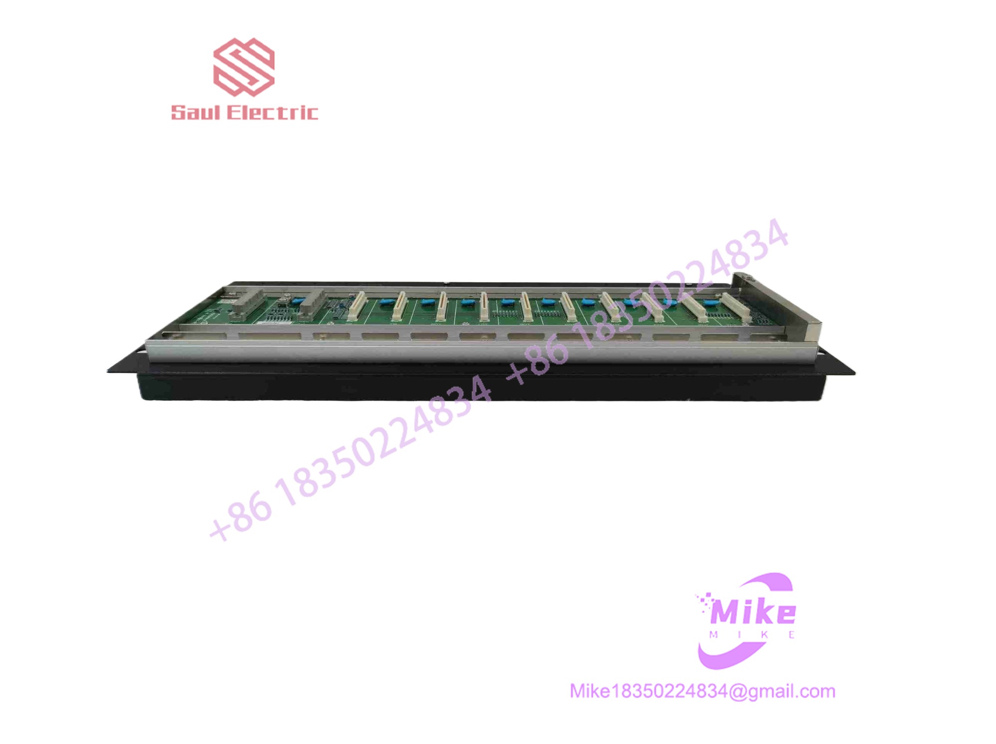
ANB11D-225/BU2A
Key Technical Specifications
| Technical Parameter | Specification Value |
| Device Type | Optical ESB Bus Node Unit (with Optical Repeater) |
| System Compatibility | Yokogawa CENTUM VP / CS 3000 DCS platforms |
| Max Transmission Distance | Up to 5 km via optical fiber connection |
| Power Supply Configuration | Dual-redundant power supply architecture |
| Nominal Supply Voltage | 220–240 V AC (Code -25 variant configuration) |
| Explosion Protection | Non-explosion protected standard variant (Code 5) |
| Connector Unit Suffix | /BU2A (ESB Bus connector unit with terminator) |
| Connectable I/O Modules | Up to 8 native FIO slots per base unit |
| Mounting Architecture | 19-inch rack-mount chassis |
Global Sourcing & Live-Test SOP (Transparency Core)
Procuring secondary market distributed control system infrastructure requires stringent optical and electrical verification. Every inbound Yokogawa optical node unit goes through a strict evaluation pipeline:
- Inbound Verification: Serial number pedigree checks against global industrial asset ledgers, microscopic inspection of optical transceiver ports, and gold-edge backplane connector audits.
- Live Simulation: Slotted directly into an authentic Yokogawa CENTUM VP test node chassis running an active optical bus topology.
- Diagnostics: Dual-rail power stability tests, 5 km optical loop attenuation verification, node-to-controller handshake validation, and a 24-hour thermal burn-in run under continuous load.
- Final Prep: Optical port cleaning with lint-free precision swabs, anti-static shielding bag placement, and heavy-duty ESD-safe vacuum sealing.
The Field Engineer’s Pitfall Guide
- ❗ Fiber Optic Core Mismatches: Connecting multi-mode versus single-mode optical jumper cables incorrectly to the repeater transceiver ports will introduce massive insertion losses and trigger instant bus timeout faults.
- ❗ Power Supply Voltage Surges: Mistaking AC-rated power supply modules for 24V DC infrastructure will instantly damage internal power distribution components upon energization.
- ❗ Optical Connector Contamination: Overlooking microscopic dust particles on the fiber optic ferrules before insertion will scatter laser light and cause intermittent packet drops across the optical ring.
Intent-Driven FAQ
- Will replacing this node unit erase my control logic or station configuration?
No. System logic and database parameters reside centrally in the Field Control Unit (FCU) and engineering station software, though node address switches must match the original layout.
- Can this optical node be maintained or swapped while the plant is live?
Online module replacement is supported for individual power supplies and I/O cards if configured for redundant maintenance mode, but swapping the core optical chassis requires proper system isolation.
- What indicates a failing optical transceiver module during troubleshooting?
Observing optical link status indicator errors or sudden communication loss while fiber power meter readings measure within normal limits points to an internal transceiver failure.
- What does the
/BU2Asuffix designate?It denotes the factory-configured internal backplane connector unit and termination layout designed specifically for secure optical ESB bus matrix integration.
- What type of warranty covers this surplus hardware?
Verified units are backed by an industry-standard replacement warranty covering electrical and optical functionality under normal operating parameters.





