


Description
Peritek AC7-00712-1113 | PMC-to-PCI Adapter Carrier Board
Dynamic Product Introduction
Integrating specialized PCI Mezzanine Cards (PMC) into traditional computer or industrial rack systems often requires physical format conversion without adding translation latency. The Peritek AC7-00712-1113 (utilizing the PMA-P passive carrier layout) solves this physical gap by providing a direct, unbridged 64-bit data pipe straight from the standard PCI bus to the mezzanine connector set.
Honestly, while active bridge cards are necessary for complex clock-speed shifting, sticking to a transparent passive adapter like this variant avoids driver compatibility headaches—provided you mind signal trace lengths and backplane load positioning. It’s an essential legacy item for keeping specialized frame grabbers, communication cards, and display processors running in older host rigs.
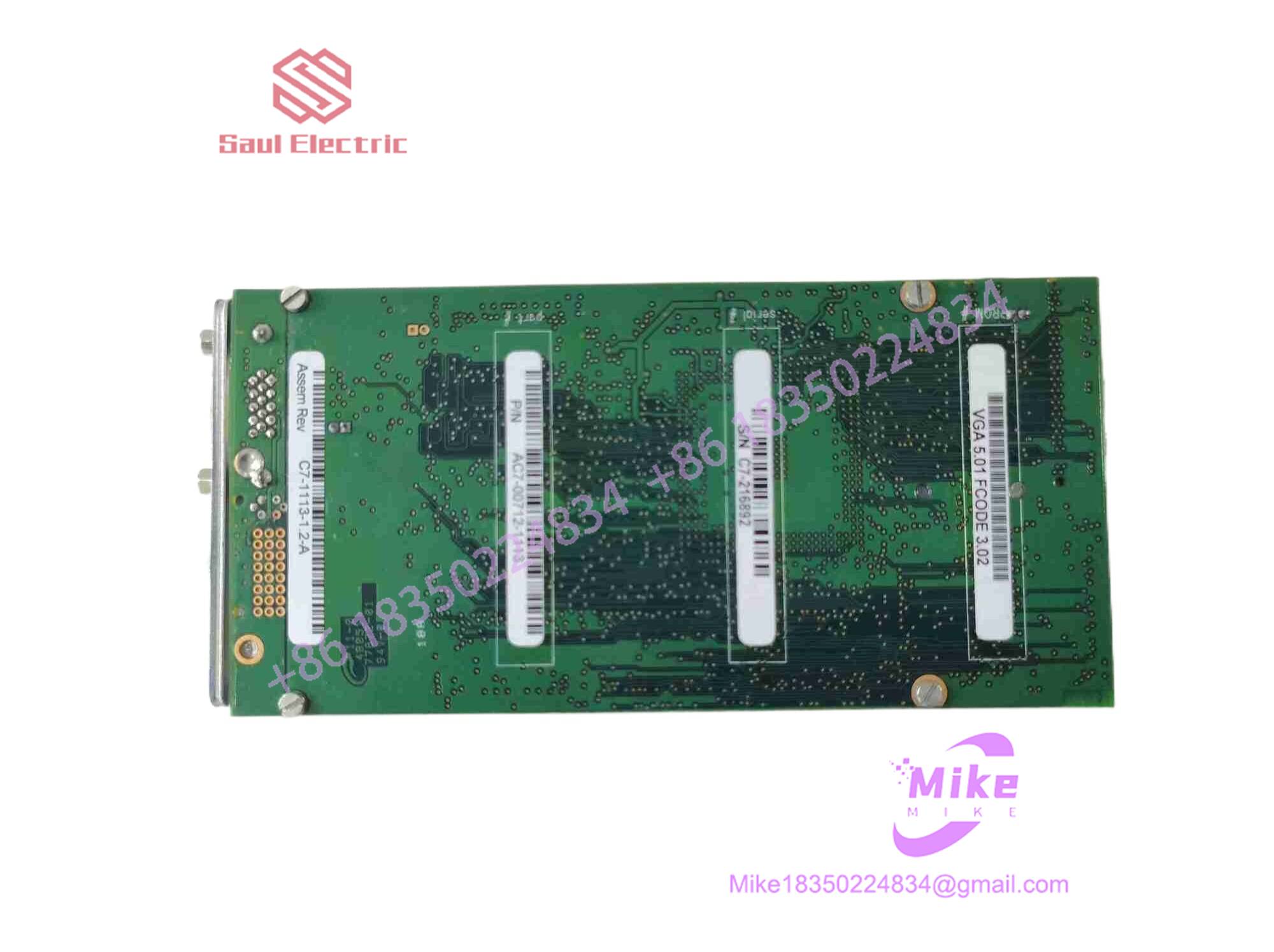
AC7-00712-1113
Key Technical Specifications
| Parameter | Specification Detail |
| Primary Architecture | PMC-to-PCI Passive Adapter (PMA-P family layout) |
| Bus Compatibility | 32-bit and 64-bit PCI Bus standard |
| Design Type | Bridgeless / Transparent Extension |
| Data Path | Full 64-bit interconnect to PMC connectors |
| Signaling Support | Configurable for 3.3V and 5V PMC environments via index pins |
| Onboard Diagnostics | Test point pins and power status LEDs (+12V, -12V, +5V, +3.3V, VIO) |
| Optional Interfaces | JTAG port connector and optional VME P2-type breakout header |
| Operating Environment | Standard commercial/industrial temperature ranges |
Global Sourcing & Live-Test SOP
Sourcing vintage or specialized mezzanine carrier boards requires careful physical inspection to ensure edge connectors and surface-mount components haven’t suffered mechanical stress or trace micro-cracks. Our quality protocol is strict:
- Inbound Verification: Board part numbers and revision stamps are cross-referenced against original Peritek manufacturing documentation. Solder joints around the heavy PMC headers are inspected under magnification.
- Live Simulation: The carrier board is loaded with a test PMC module and mounted onto a validated PCI test backplane to confirm physical seating security and correct power plane distribution.
- Diagnostics: We verify rail voltage stability using the onboard test points, checking that +5V, +3.3V, and auxiliary rails are clean and free of excessive ripple before checking data pass-through continuity.
- Final Prep: Approved units are cleaned with high-purity solvent, fitted with protective edge guards, and sealed in heavy anti-static moisture-barrier bags.
The Field Engineer’s Pitfall Guide
❗ Overlooking Backplane Position: Because the PMA-P design is completely passive (bridgeless), it creates longer signal traces than standard motherboards. Installing multiple cards or placing this adapter near the middle of a heavily populated backplane segment will cause signal reflections and timing faults. Always mount it at the end slot farthest from the CPU.
❗ 66 MHz System Limitations: Trying to force this passive board into a high-speed 66 MHz PCI slot can trigger severe data corruption. For high-clock environments, ensure you are utilizing an active bridged carrier model (such as the PMB-P) instead.
❗ Missing Local 3.3V Generation: Some older host systems fail to supply adequate 3.3V power rails to the standard PCI slot. Verify your host backplane’s supply capabilities or ensure local regulation jumpers are properly set before powering up a 3.3V-dependent PMC card.
Intent-Driven FAQ
What does the AC7-00712-1113 part number represent?
This part number identifies a specific manufacturing run/assembly variant of Peritek’s PMA-P series passive PMC-to-PCI adapter boards.
Does this adapter require specialized software drivers?
No. Because the board features a passive, bridgeless design that maps the PCI bus straight through to the mezzanine card, it is completely transparent to the operating system; only the target PMC module itself requires appropriate drivers.
Can I plug a 32-bit PMC card into a 64-bit slot using this carrier?
Yes, the mechanical and electrical layout accommodates standard interchangeability features built into the PCI/PMC specifications, though data width scaling will match the limitations of the installed mezzanine device.
What are the onboard LEDs used for?
The integrated power LEDs provide immediate visual confirmation that your system backplane is successfully delivering required power rails (+5V, +3.3V, +12V, -12V, and VIO) to the carrier interface.
What warranty covers surplus Peritek carrier boards?
Every unit shipped from our inventory is backed by a comprehensive 12-month operational warranty covering trace continuity, connector pin integrity, and power distribution reliability.





