

Description
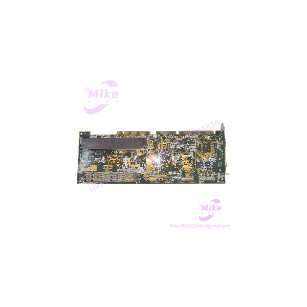
Macrotek MSPC-68866800 | Control Board Module, Industrial Automation
Architect’s Product Breakdown
The Macrotek MSPC-68866800 functions as a specialized control board module built for demanding industrial automation and electronic process management environments. This hardware coordinates signal routing, system monitoring, and low-level logic processing to ensure synchronized operation across interconnected machinery nodes.
Implementing this component requires strict adherence to electrostatic discharge protocols during handling and installation. Technicians must verify backplane pin alignment and connector seating to prevent intermittent communication errors or hardware damage. Environmental factors such as cabinet humidity and ambient operating temperature must also stay within rated industrial thresholds to preserve internal component longevity.
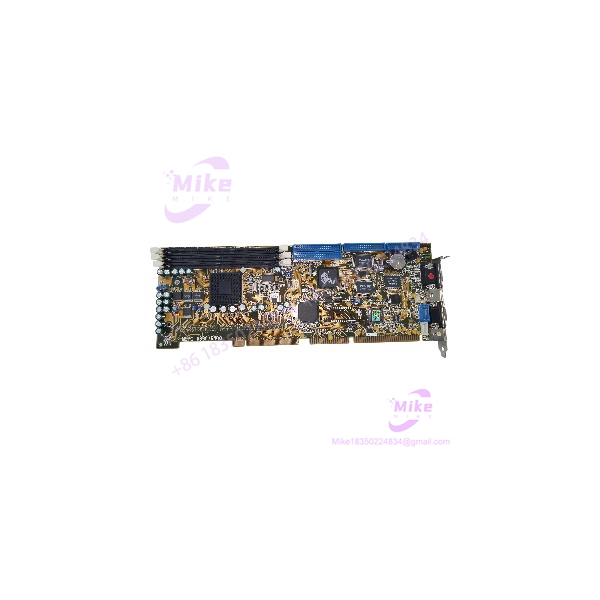
MSPC-68866800
Key Technical Specifications
| Parameter | Specification |
| Module Type | Control Board / Logic Module |
| Circuit Board Design | Multi-layer SMT / Thru-hole hybrid |
| Operating Voltage | Standard Industrial DC Rails |
| Mounting Style | Rack / Chassis Mount |
| Ambient Operating Temperature | 0°C to 60°C |
| Storage Temperature | -40°C to 85°C |
| Humidity Tolerance | 5% to 95% RH (non-condensing) |
| Enclosure Compatibility | IP20 Open-style industrial chassis |
Field Engineer’s Pitfall Guide
- WARNING: Electrostatic Discharge Vulnerability. Never handle the bare circuit board without a grounded wrist strap. I have seen fresh out-of-box controller modules instantly suffer micro-processor gate failure due to static discharge from synthetic clothing in dry winter conditions.
- WARNING: Unverified Backplane Pins. Inspect the card-edge and backplane pins for minor bends before insertion. Forcing a misaligned module will sheer delicate receptacle pins, leading to extensive downtime while replacing the entire backplane assembly.
- WARNING: Firmware/Revision Mismatches. Verify that replacement boards match the exact hardware revision of neighboring modules on shared communication rings to prevent bus timeouts.
QA & Testing SOP
- Visual & Origin Verification: Inspect the PCB for solder bridging, component stress fractures, and verify OEM serialization against factory traceability records.
- Static Control Audit: Ensure the module is handled exclusively within ESD-safe workstations utilizing continuous surface grounding monitors.
- Power-On Bench Test: Insert the module into a dedicated test fixture to verify clean DC power rail distribution and proper processor boot behavior.
- Signal Handshake Validation: Run diagnostic routines to test onboard memory integrity and input/output communication ports.
- Packaging: Enclose in metalized static-shielding bags and pack with high-density anti-static foam.
Technical FAQ
Can I hot-swap this control module while the main system power is active? No. Power must be completely isolated from the rack or chassis before inserting or removing this board to prevent electrical arcing and component burnout.
Does this module require battery backup for internal memory retention? Depending on the specific system configuration variant, volatile logs may rely on a board-mounted lithium cell or supercapacitor which should be checked prior to commissioning.
What tools are necessary to verify signal integrity during installation? A calibrated digital multimeter for power rail checks and a designated diagnostic terminal or software tool matching the system family are required.
Is field-level repair or component soldering recommended on this board? No. Due to multi-layer surface-mount construction, component-level field repairs are not advised; faulty modules should be replaced as a complete unit.





