

Description
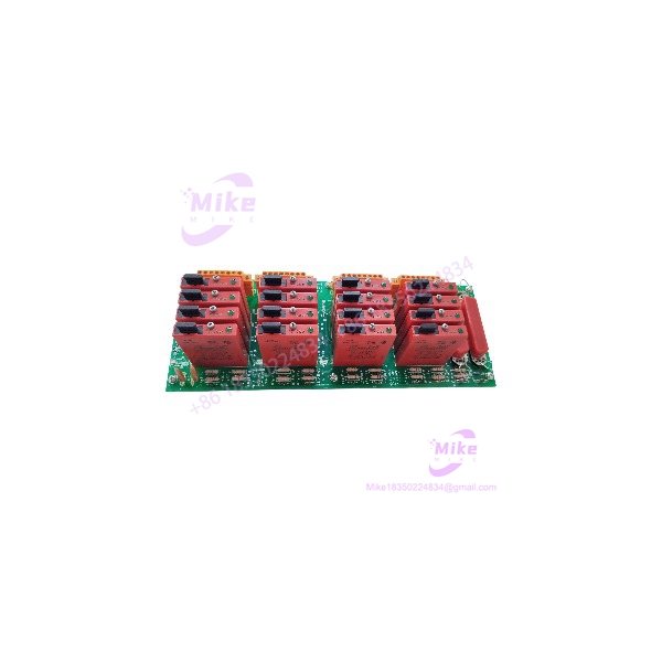
Honeywell MC-TDOD14 | 16-Channel Solid-State DO
Product Introduction
When a process valve, solenoid, relay, or other DC field actuator suddenly stops responding, the failed component is not always the field device. In a legacy Honeywell cabinet, the signal path runs through several layers of I/O hardware, and the Field Termination Assembly is one of the places worth checking. MC-TDOD14 provides the field-side termination for the corresponding solid-state digital-output architecture.
The Honeywell MC-TDOD14 51309153-175 is specifically documented as a 3–30 VDC solid-state digital-output FTA. It provides 16 output channels, uses compression terminals, and carries conformal coating. That makes the exact part number important: the nearby MC-TDOD13, MC-TDOD23, and MC-TDOD54 references represent different output-voltage or terminal configurations.
This is field-interface hardware, not the digital-output processor itself. Verify the associated IOP, cabinet drawings, field load voltage, terminal style, and system revision before substitution.
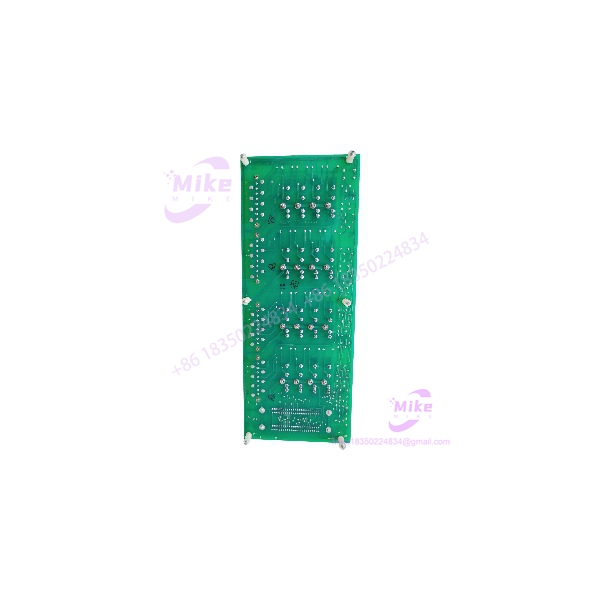
MC-TDOD14 51309153-175
Key Technical Specifications
- Manufacturer: Honeywell
- Model: MC-TDOD14
- Part Number: 51309153-175
- Product Type: Digital Output Field Termination Assembly
- FTA Classification: 3–30 VDC solid-state digital output
- Number of Channels: 16
- Output Category: Solid-state DC digital output
- Field Voltage Range: 3–30 VDC
- Terminal Type: Compression terminals
- Mounting Size: Size B
- PCB Protection: Conformal coating
- Compliance Version: CE compliant
- System Application: Honeywell PM I/O / Process Manager and related legacy control architectures
- Interface Role: Field termination between the digital-output I/O processor and discrete field loads
Honeywell documentation specifically lists the MC-TDOD14 as the CE-compliant 51309153-175 variant. The same documentation distinguishes it from MC-TDOD13, which uses the 51304650-150 non-CE part number.
Application Scenarios & Pain Points
Solenoid and Actuator Control
A digital-output channel may command a solenoid valve, relay, contactor interface, indicator, or another binary field device. If one of those commands disappears, maintenance has to determine whether the fault sits in the controller logic, I/O processor, FTA, field wiring, or load.
MC-TDOD14 occupies the field-termination portion of that chain.
The 3–30 VDC specification is the first boundary condition to check. A load outside that range should not be connected simply because the connector fits.
Legacy Process Manager Maintenance
With the correct FTA: Existing field wiring can remain associated with the established Honeywell I/O architecture.
With the wrong FTA: The terminal arrangement or output-voltage class may not match the cabinet design, creating additional commissioning work.
That is why 51309153-175 should be treated as an identification requirement, not merely a catalog cross-reference.
16-Channel Discrete Output Cabinet
The MC- provides 16 output terminations in the documented Size B format. That density is useful for cabinets controlling groups of binary field devices where multiple solenoids, relay interfaces, and actuator commands are concentrated in one I/O section.
Legacy Hardware Migration
The MC- belongs to the Honeywell PM I/O hardware ecosystem, which means migration work requires more than matching a field-voltage specification.
If a plant is migrating from legacy Honeywell I/O to another architecture, document every channel, load type, polarity, common arrangement, and fail-state requirement before removing the existing FTA. Otherwise, the migration can turn into a channel-by-channel troubleshooting exercise.
QA & Live Testing SOP
For Honeywell MC- 51309153-175, incoming inspection should establish both identity and electrical condition.
- Identity verification: Confirm and 51309153-175 on the physical unit.
- Revision recording: Photograph and record PCB, assembly, and manufacturing markings.
- Terminal inspection: Examine all compression terminals for damage, looseness, corrosion, or previous overheating.
- PCB inspection: Check for burned components, cracked solder joints, contamination, corrosion, and evidence of unauthorized repair.
- Conformal-coating inspection: Look for damaged, missing, cracked, or contaminated coating.
- Output-path inspection: Verify continuity and appropriate isolation before connecting field loads.
- Controlled energization: Test using an appropriate Honeywell-compatible test setup with current-limited instrumentation.
- Channel testing: Exercise representative output channels rather than declaring the entire unit good after a single-channel check.
- Load simulation: Where practical, use an appropriate test load to confirm switching behavior across representative output channels.
- System test: Verify recognition and operation through the compatible digital-output processor.
- ESD packaging: Store and ship the FTA in antistatic packaging with adequate mechanical protection.
A power-on test is not enough. For a digital-output FTA, the useful question is whether the output path actually switches the expected field-side voltage under a controlled test condition.
Field Engineer’s Pitfall Guide
❗ Do not substitute MC-TDOD13 by appearance. Honeywell documentation identifies MC-TDOD13 as a related 3–30 VDC solid-state digital-output FTA, but its CE/non-CE part-number configuration differs. MC-‘s CE-compliant identifier is 51309153-175.
❗ Do not confuse MC- with MC-TDOD23. Both are solid-state digital-output FTAs, but MC-TDOD23 is specified for the 31–200 VDC class. MC- is the 3–30 VDC version. That is not a cosmetic distinction.
❗ Do not confuse MC- with the I/O processor. The FTA provides the field termination/interface function. The associated digital-output processor supplies the control-system I/O processing. A matching FTA alone does not constitute a complete digital-output channel.
❗ Check the field load before energizing. A solenoid or relay may draw considerably more current than expected during energization. Verify the actual load and the applicable Honeywell I/O specifications rather than assuming every 24 VDC device is acceptable.
And one veteran-maintenance rule: photograph the terminal wiring before removal. Sixteen channels are manageable. Sixteen unlabeled wires after a rushed shutdown are not.
Intent-Driven FAQ
What is Honeywell MC-?
The Honeywell MC- is a 3–30 VDC solid-state Digital Output Field Termination Assembly with 16 channels. The CE-compliant part number is 51309153-175.
What is the part number for MC-?
The CE-compliant part number is 51309153-175. Honeywell’s hardware planning documentation lists MC- directly against this number.
How many output channels does MC- have?
16 channels. Honeywell’s planning documentation specifies 16 channels and Size B mounting for this FTA.
What voltage does MC- support?
The documented output class is 3–30 VDC solid-state digital output. Do not confuse this with the related MC-TDOD23, which belongs to the 31–200 VDC output class.
Does MC- use compression terminals?
Yes. Honeywell documentation specifies compression terminals for MC-. This is one of the identification points to verify before installing a replacement.
Is MC- the same as MC-TDOD54?
No. Both are associated with the 3–30 VDC solid-state digital-output family, but Honeywell’s hardware planning information differentiates their terminal configurations. MC- is the compression-terminal version, while MC-TDOD54 is the corresponding screw-terminal configuration.
Is MC- compatible with every Honeywell Experion system?
No. Compatibility depends on the installed I/O architecture, digital-output processor, FTA cabling, cabinet configuration, and system generation. Verify the complete I/O chain rather than matching only the model number.
Can I hot-swap MC-?
Do not assume it can be hot-swapped. Follow the maintenance procedure for the specific Honeywell cabinet and I/O architecture. If live FTA replacement is not explicitly permitted, isolate the applicable equipment before removal.
How should a surplus MC- be tested?
First verify MC- / 51309153-175, then inspect the PCB, conformal coating, terminals, and connectors. Next, perform controlled electrical checks and exercise representative digital-output channels with an appropriate test setup. Ideally, verify the assembly through the compatible Honeywell I/O processor before releasing it for production use.
What should I verify before purchasing?
Verify the model, 51309153-175 part number, 3–30 VDC output class, 16-channel configuration, compression-terminal arrangement, and associated I/O processor. Also establish whether the offered unit is new factory stock, new surplus, refurbished, or used.
What warranty should I expect?
Warranty depends on the supplier and the condition of the individual unit. Ask for written coverage before purchase and distinguish supplier warranty from OEM warranty. For obsolete DCS hardware, also confirm whether the warranty covers functional failure discovered after installation and commissioning.





