

Description
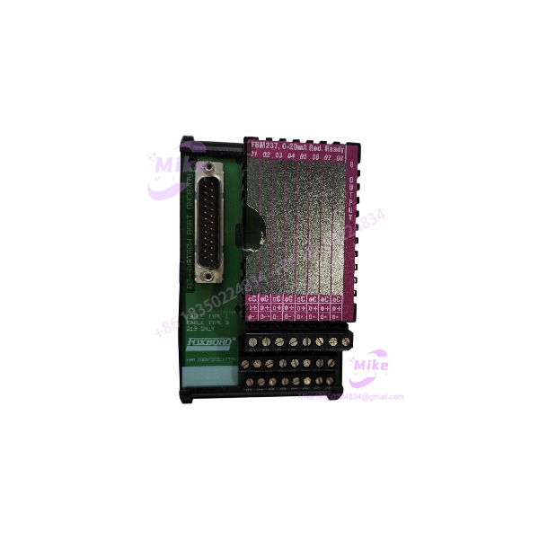
Foxboro PBCO-D8-009 | FBM Interface Module New In Stock
Architect’s Product Breakdown
The Foxboro PBCO-D8-009 operates as a dedicated marshalling and termination interface within distributed control architectures, bridging standard Foxboro FBM I/O cards (such as the FBM211, FBM207b, FBM241c, and FBM242) with intrinsically safe isolation barriers. In heavy process industries like oil, gas, and chemical refining, cleanly separating hazardous area field wiring from safe-area control electronics is mandatory to prevent fault propagation. This board consolidates multi-core instrumentation wiring via compression screw terminals while maintaining clean backplane communication links through a standard 37-pin D-Sub connection.
Deploying this module requires strict attention to loop power distribution and shielding integrity. The board features dual redundant 24 VDC power terminal blocks protected by time-lag fuses, complete with automatic OR-ing diodes and voltage fault detection relays. When replacing or installing this termination assembly during a plant shutdown, technicians must verify that the shield ground rail and earth bonding screw are properly secured to prevent common-mode electrical noise from corrupting low-level analog or digital field signals.
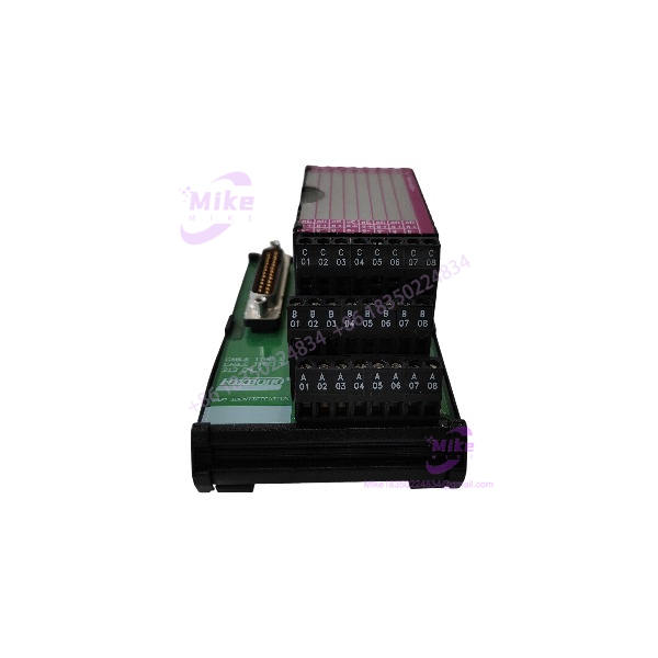
PBCO-D8-009
Key Technical Specifications
- Manufacturer: Foxboro / G.M. International Partner Design
- Product Category: Termination Board (TB) / Interface Module
- Capacity: 8 isolation module positions (supporting up to 16 channels, e.g., 16 AI, 16 DI, or 8 DI / 8 DO)
- FBM Interface: 37-pole male D-Sub connector
- Nominal Supply Voltage: 24 VDC (range: 20 to 30 VDC), reverse-polarity protected with redundant inputs
- Fuse Protection: 2A time-lag replaceable fuse (with onboard spare)
- Fault Signaling: Voltage-free SPDT relay contact (de-energized on fault condition)
- Operating Temperature Range: -20°C to +60°C
- Relative Humidity Limit: Up to 90% non-condensing (at <35°C)
- Mounting Type: Surface mounting via four M6 assembly slots on painted carbon steel support
- Dimensions / Weight: Width 224 mm, Depth 190 mm, Height 122 mm; Approximately 940 g
Field Engineer’s Pitfall Guide (Unique Value)
- Overlooking Power Fault Relay Logic: Failing to wire the onboard fault-signaling SPDT relay contact into your cabinet alarm loop means a blown 2A supply fuse or a drop below 18 VDC will go unnoticed by operators until field loops start failing.
- Improper Shield Rail Bonding: I’ve spent hours debugging erratic analog readings caused by technicians floating the cable screen. Ensure the drain wires are firmly tied to the dedicated M5 shield rail rather than relying on random panel ground paths.
- Mismatched FBM Cable Pinouts: When attaching the 37-pin D-Sub system cable, verify that the cable matches the exact FBM variant type (e.g., FBM211 vs. FBM242). Forcing an incorrect cable layout can short logic supply rails across the barrier interface.
QA & Testing SOP (Transparency)
- Visual & Origin Verification: Units undergo structural inspection for paint integrity on the carbon steel chassis, secure D-Sub pin alignment, and correct OEM labelling.
- Live Test Bench Environment: Boards are mounted on a test rig powered by dual redundant 24 VDC supplies to verify power bus distribution and OR-ing diode performance.
- Diagnostic & Fault Testing: Technicians simulate low-voltage conditions (<18 VDC) to confirm proper SPDT fault relay trip behavior and test continuity across every signal path.
- Anti-Static & Protective Packaging: Post-inspection, units are securely packed in industrial-grade protective material to prevent physical damage to terminal blocks and electronic components during transit.
Technical FAQ
Can I hot-swap field wiring on the PBCO-D8-009 while the system is powered?
While the plug-in disconnect screw terminal blocks allow individual wire isolation, always exercise caution on powered loops to prevent inductive voltage spikes or accidental short circuits across active 24 VDC lines.
Does this termination board provide intrinsic safety isolation by itself?
No. The PBCO-D8-009 acts as a marshalling and distribution platform; intrinsic safety and galvanic isolation are handled by the associated D1000 series safety modules mounted directly to it.
What causes the red fault LED to illuminate on the termination board?
The red LED triggers when the incoming supply voltage drops below 18 VDC or when the primary protection fuse is blown. Check your incoming power rails and inspect the 2A time-lag fuse.
What is the standard warranty status for surplus inventory units?
Verified surplus or new-in-box termination boards typically carry a 12-month operational warranty covering material and manufacturing defects under normal industrial conditions.





