

Description
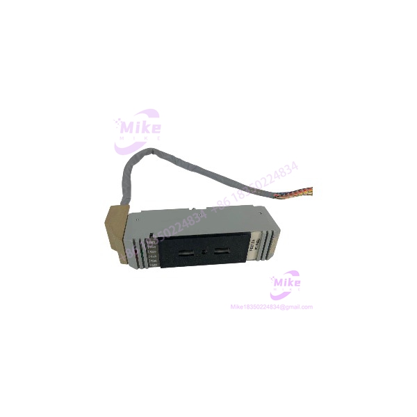
FOXBORO P0500RU | I/A Series DCS Module
Architect’s Product Breakdown
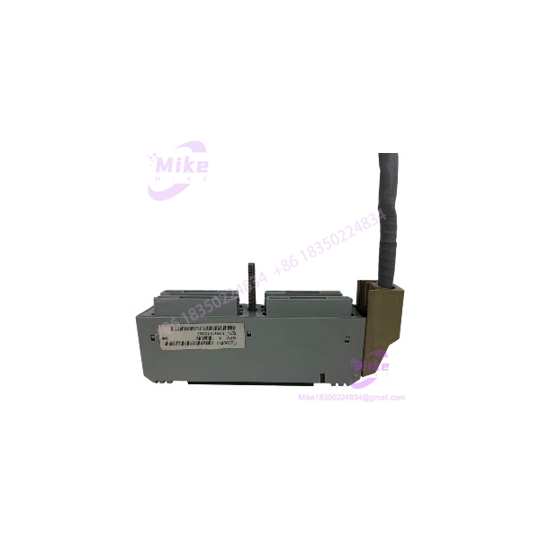
The FOXBORO P0500RU is most consistently identified in specialist parts catalogs as the FBM3A/33A termination cable assembly for the Foxboro I/A Series distributed control system. This is a connection component, not a standalone PLC CPU or analog input module. Its job is to provide the physical termination and connection path required by the corresponding fieldbus module installation.
For maintenance engineers, the distinction matters. Ordering P0500RU when the actual requirement is an FBM, a terminal plug, or a different termination assembly can leave a shutdown repair incomplete. Check the existing cable’s connector arrangement, termination type, required length, and installed FBM designation before placing the order. Supplier documentation identifies a 37-pin male D-sub connector and cable lengths up to 30 meters for the FBM3A/33A assembly family. Confirm that these details match the specific unit being offered.
The P0500RU is associated with legacy Foxboro I/A Series installations, so replacement decisions should be based on the installed hardware documentation rather than a broad claim of compatibility with all I/A Series systems. Because this is a physical interconnection component, cable pinout, termination style, and connector condition are more relevant than processor firmware or logic execution time.
P0500RU
Key Technical Specifications
| Parameter | Specification |
|---|---|
| Manufacturer | FOXBORO / Invensys |
| Model | P0500RU |
| Associated assembly | FBM3A/33A |
| Product type | Termination cable assembly / terminal connection component |
| System family | Foxboro I/A Series DCS |
| Connector | 37-pin male D-subminiature, reported for the assembly |
| Cable length | Up to 30 m (98 ft), depending on assembly configuration |
| Termination type | Type 1 designation reported; verify against the applicable wiring documentation |
| Cable materials | Supplier listings mention polyurethane or Hypalon/XLP |
| Supply voltage | Not established as a standalone electrical rating for the cable assembly |
| Communication protocol | Determined by the connected hardware and wiring configuration; do not assume Ethernet or Modbus TCP |
| Operating temperature | Verify the specific assembly’s manufacturer documentation |
| Lifecycle | Legacy component; confirm OEM support status |
| Condition | Confirm actual stock condition and functional inspection records |
The connector and cable information above comes from specialist reseller listings, not a verified current OEM datasheet.
Field Engineer’s Pitfall Guide
Warning 1 — Verify the connector and pinout before installation.
A matching P0500RU label is not sufficient if the supplied cable has a different connector arrangement or termination configuration. Compare the existing cable assembly and approved wiring drawing before connecting it to the FBM installation.
Warning 2 — Do not confuse a termination cable with a fieldbus module.
The P0500RU is listed as an FBM3A/33A termination cable assembly. It should not be treated as a substitute for the electronic fieldbus module itself. If a controller reports an I/O module fault, establish whether the failure is in the FBM, terminal hardware, cable, or field wiring before ordering parts.
Warning 3 — Inspect cable condition and routing.
On older installations, connector damage, stressed cable bends, poor shielding practices, and degraded insulation can create intermittent faults that resemble module failures. Inspect the entire cable path, connector contacts, strain relief, and grounding or shielding arrangement according to the site’s wiring standards.
Field scenario: A replacement cable arrives during a planned maintenance window, but the connector and termination arrangement do not match the installed assembly. The control team cannot complete the repair until the correct cable is sourced. A photograph of the nameplate and both connector ends before purchasing would have prevented the mismatch.
QA & Testing SOP — Transparency
1. Visual and origin inspection
- Confirm the P0500RU and FBM3A/33A identification markings.
- Inspect cable insulation, connector contacts, strain relief, and signs of corrosion or mechanical damage.
- Record serial or lot information where available and review supplier traceability documents.
2. Physical and electrical inspection
- Verify connector type, cable length, termination arrangement, and pinout against the approved drawing.
- Perform continuity and short-circuit checks where appropriate, using the correct test procedure.
- Inspect shielding and grounding provisions where applicable.
3. System compatibility
- Confirm the associated FBM hardware and termination requirements.
- Check that the replacement matches the existing installation before connecting it to an energized control system.
4. Test documentation
- Record the inspection results and any limitations.
- Do not claim a successful live DCS test unless the actual assembly has been tested in a suitable environment.
5. Packaging
- Protect connectors from impact and contamination.
- Use appropriate ESD precautions where the assembly or connected electronic components require them.
- Document the supplied condition and warranty terms.
Technical FAQ
Q1. Is FOXBORO P0500RU an I/O module?
No. Specialist listings identify it as the termination cable assembly associated with FBM3A/33A hardware. Confirm the physical assembly before ordering.
Q2. Can I use P0500RU with any Foxboro I/A Series fieldbus module?
No universal compatibility should be assumed. Verify the FBM model, termination assembly, connector arrangement, and approved wiring documentation.
Q3. Does P0500RU require a firmware upgrade?
A termination cable assembly does not ordinarily require a firmware flash. Firmware requirements, if any, belong to the electronic modules or controllers connected to it.
Q4. Can I replace P0500RU while the process is running?
Do not disconnect or reconnect the assembly on an operating system without an approved site procedure. The consequences depend on the connected fieldbus architecture, affected I/O, redundancy, and process safety requirements.





