

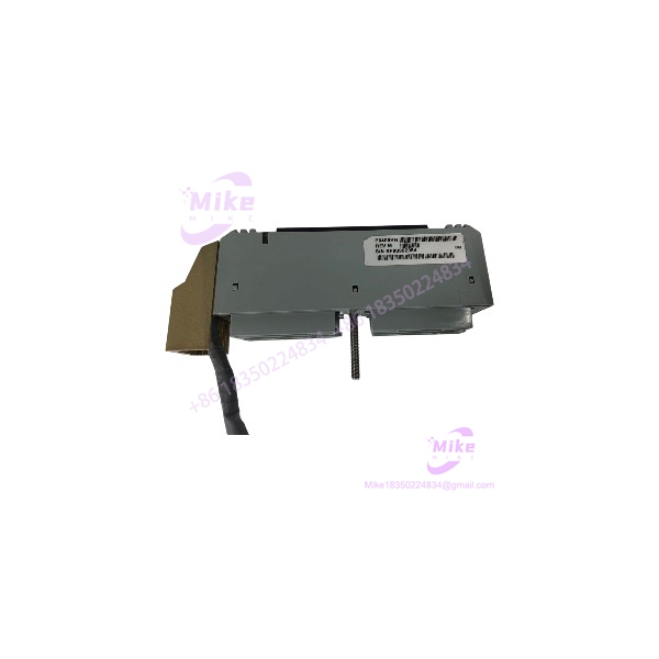
Description
Foxboro P0400HH Industrial Control System Cable Assembly
Product Introduction
The Foxboro P0400HH is used in the field-wiring interface of legacy Foxboro I/A Series distributed control systems. Its termination-cable designation is supported by supplier catalogs and Foxboro technical documentation.
A Foxboro wiring guideline specifically lists P0400HH as a nosecone cable part number and gives different electrical characteristics depending on the associated module: 50 ohms for FBM01 resistance and 200 ohms for FBM43 impedance. These are application-specific cable/interface figures, not a general power or signal rating for the cable.
That distinction matters when replacing a cable in an existing analog measurement loop. A mechanically compatible cable is not necessarily electrically interchangeable across every FBM configuration.

P0400HH
Key Technical Specifications
| Parameter | Available information |
|---|---|
| Manufacturer | Foxboro |
| Part number | P0400HH |
| Product type | Termination cable assembly |
| Associated modules | FBM01 and FBM43 references in technical documentation |
| System family | Foxboro I/A Series |
| FBM01-related resistance | 50 ohms, per cited wiring guideline |
| FBM43-related impedance | 200 ohms, per cited wiring guideline |
| Revision examples | Rev. L and Rev. M appear in supplier records |
| Connector configuration | Verify against the actual assembly |
| Cable length and wire gauge | Not independently verified |
| Operating temperature | Not independently verified |
Sources:
Specification caution: Do not use generic third-party pages that describe P0400HH as a pressure transmitter, analog output module, or standalone I/O module. The stronger evidence identifies it as a cable assembly.
Application Scenarios & Pain Points
Legacy FBM maintenance
Replacing a damaged or missing termination cable can help restore an existing field-wiring arrangement without changing the installed module architecture. Confirm whether the cable is intended for the FBM01 or FBM43 application in question.
Analog loop troubleshooting
Cable and interface resistance can affect loop loading and measurement conditions. Use the applicable Foxboro wiring guideline to check the actual loop configuration before substituting a cable.
Obsolete spare-parts sourcing
For legacy installations, a verified surplus assembly may be more practical than redesigning a field interface. Inspect connector condition, revision markings, continuity, and supplier test evidence before acceptance.
These are typical maintenance scenarios for this cable category, not a guarantee of compatibility with every Foxboro installation.
QA & Live Testing SOP
- Confirm the part identity. Verify the P0400HH label and any revision marking. The listing should identify a cable assembly, not just a module associated with the same system.
- Inspect both ends. Check connector type, contact condition, locking features, strain relief, insulation, and any signs of corrosion or repairs.
- Check the application. Determine whether the installed hardware is FBM01, FBM43, or another configuration documented for the assembly.
- Verify electrical characteristics. Consult the applicable Foxboro manual and confirm that the cable’s resistance or impedance is appropriate for the intended circuit.
- Perform approved bench checks. Use a suitable meter and the approved test procedure to check continuity and unintended shorts. Do not apply test voltages that could damage connected electronics.
- Validate after installation. Follow the site’s approved commissioning procedure and confirm stable operation of the affected signals before returning the loop to service.
- Retain acceptance records. Record the supplied part number, revision, inspection results, test evidence, and any warranty or return conditions.
Do not disconnect or reconnect control-system wiring in a live process unless the site’s procedures and equipment documentation explicitly permit it.
Field Engineer’s Pitfall Guide
- Do not confuse a cable with an FBM module. P0400HH is identified as a termination cable; it is not the same item as the FBM01 or FBM43 electronics.
- Do not ignore module-specific electrical characteristics. The cited guideline distinguishes FBM01 resistance from FBM43 impedance. Confirm the intended application before substituting.
- Do not assume revision markings are interchangeable. Rev. L and Rev. M appear in supplier records, but interchangeability should be established from the applicable documentation.
- Do not judge compatibility by connector appearance alone. Verify pinout, wiring function, and the required cable/interface characteristics.
- Do not accept “tested” without details. Request the actual continuity or functional-test scope and clarify whether the cable has been inspected or repaired.
Intent-Driven FAQ
Q1: What is the Foxboro P0400HH?
It is a Foxboro I/A Series termination cable assembly associated with FBM01/FBM43 field-wiring applications.
Q2: Is P0400HH an analog output module?
The more reliable evidence identifies it as a cable assembly, not an analog output module. Some reseller listings appear to misclassify it.
Q3: What are the electrical characteristics?
The Foxboro wiring guideline lists 50 ohms for FBM01 resistance and 200 ohms for FBM43 impedance for P0400HH. These figures must be applied in the correct documented context; they are not interchangeable specifications.
Q4: Can P0400HH Rev. L replace Rev. M?
Do not assume so based on the part number alone. Check the applicable Foxboro documentation and compare the assembly’s markings and connector arrangement.
Q5: What should I ask the supplier before ordering?
Request clear photographs of the label and both ends, the revision, confirmation of the intended FBM application, physical condition, continuity-test results, and the return policy.





