

Description
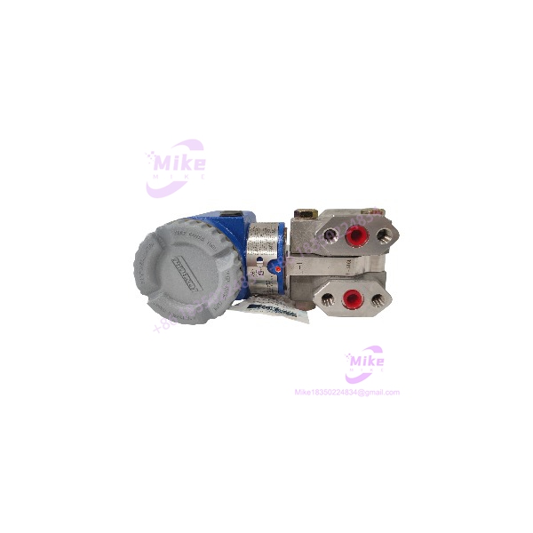
Foxboro IDP10-A22A01F-M1 | Differential Pressure Transmitter
Product Introduction
When a differential-pressure transmitter is embedded in a running process, replacing it is not simply a matter of matching the brand and wiring. The sensor range, process interface, output behavior, and installation details all have to align with the control loop. The Foxboro IDP10-A22A01F-M1 is an I/A Series transmitter designed to measure differential pressure and provide a 4–20 mA signal to the receiving control system.
This specific model is associated with 316 stainless-steel process covers, a 316L sensor, silicone fill fluid, and tapped 1/4-inch NPT process connections. Those details are useful for preliminary sourcing, but they do not establish the calibrated range or the condition of a particular surplus unit. Before installing an IDP10-A22A01F-M1 as a replacement, compare its complete nameplate and calibration information against the existing instrument and loop documentation.
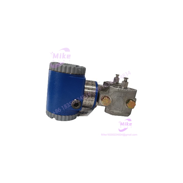
IDP10-A22A01F-M1
Key Technical Specifications
- Manufacturer: Foxboro
- Series: I/A Series
- Model: IDP10-A22A01F-M1
- Measurement Type: Differential pressure
- Output Signal: 4–20 mA analog
- Electrical Configuration: Two-wire transmitter
- Sensor Material: 316L stainless steel
- Process Cover Material: 316 stainless steel
- Fill Fluid: Silicone
- Process Connection: Tapped for 1/4-inch NPT
- Conduit Entry: 1/2-inch NPT
- Supply Voltage: IDP10 family documentation specifies 11.5–42 VDC; verify applicable model documentation and loop requirements.
- Nominal Range Code: The IDP10 “A” sensor code is associated with a 0.5–30 inH₂O span capability. This is not confirmation of the individual unit’s factory-calibrated range.
- Maximum Working Pressure: Confirm from the transmitter nameplate and applicable model documentation before installation.
- Calibration: Unit-specific LRV/URV and calibration status must be verified from the nameplate, test record, or bench calibration.
- Configuration Scope: Transmitter; manifold, mounting bracket, process tubing, and other accessories are not assumed included.
Global Sourcing & Live-Test SOP
A discontinued transmitter deserves a disciplined incoming inspection. A clean housing or matching model label does not establish measurement accuracy.
Incoming Verification
- Confirm the complete model code: -A22A01F-M1.
- Photograph the nameplate, serial number, calibration range, and any auxiliary specification codes.
- Inspect the process covers, sensor body, housing, conduit entry, and terminal compartment.
- Check for corrosion, impact damage, evidence of process-fluid ingress, or disturbed fasteners.
- Confirm that the supplied unit matches the purchase order and stated condition.
Authenticity & Traceability
- Review OEM markings, labels, serial information, and available supplier documentation.
- Compare the model code with Foxboro documentation.
- Record any missing, altered, or inconsistent identification.
- Do not represent a unit as factory-new or factory-sealed without supporting evidence.
Electrical & Functional Testing
- Inspect terminal condition and accessible wiring connections.
- Verify supply and loop configuration against the applicable documentation.
- Where equipment is available, perform a controlled 4–20 mA loop test using an appropriate pressure calibrator.
- Check zero and span response against the unit’s documented calibration range.
- Record as-found readings before making adjustments.
- Document as-left readings if calibration is performed.
- Do not claim a successful functional test unless the specific unit has been tested and the results recorded.
Extended Test & Records
- Perform an extended operating test only when a suitable, approved test setup is available.
- Record the actual duration, test conditions, and results.
- Preserve calibration records, inspection findings, and any deviations from the requested configuration.
- Firmware or PLC-style configuration records are not assumed applicable to this analog transmitter.
Packaging & Shipment
- Protect process ports and electrical connections against impact and contamination.
- Use suitable industrial packaging to prevent movement during transit.
- Include available calibration and inspection documentation.
- Clearly identify the actual supplied condition and any excluded accessories.
Procurement note: Stock status, unit condition, calibration, warranty, and return terms are seller-specific. Confirm these before purchase rather than relying on the model designation alone.
Field Engineer’s Pitfall Guide
❗ Do not assume the calibrated range from the model code alone. The family supports multiple differential-pressure spans. Verify the individual transmitter’s calibrated LRV and URV against the process requirement before commissioning.
❗ Confirm the complete process interface and installation arrangement. The documented 1/4-inch NPT tapped process connection is a key sourcing detail, but it does not confirm that a manifold, bracket, impulse tubing, or required adapters are included. Check the installed assembly before ordering a bare transmitter.
❗ Do not treat a 4–20 mA output as proof of drop-in compatibility. Confirm loop power, receiving input configuration, scaling, calibration, and hazardous-area requirements. A transmitter that produces a valid current signal can still be unsuitable for the installed application.
Intent-Driven FAQ
Q1: What is the Foxboro -A22A01F-M1?
It is an I/A Series electronic differential-pressure transmitter with a two-wire 4–20 mA analog output.
Q2: Is the discontinued?
Industrial resellers list this model as discontinued. Verify current OEM support and approved replacement options before planning a long-term migration.
Q3: Can I use this model as a direct replacement for another transmitter?
Not without comparing the full model code, calibrated range, process connections, output, and installation requirements. Similar family names do not guarantee equivalent configuration.
Q4: Does the model number confirm the calibrated pressure range?
No. The sensor range code provides useful family-level information, but the actual calibrated range should be verified from the nameplate or calibration documentation.
Q5: Does the transmitter include a manifold or mounting bracket?
Not by default. The offer should explicitly identify any included manifold, bracket, or other accessories. A transmitter-only unit should not be treated as a complete installation assembly.
Q6: Is the hot-swappable?
Do not assume so. Isolate the loop and process connections as required by site procedures, and follow the applicable Foxboro installation and maintenance instructions before removal or replacement.
Q7: What should I request when buying a surplus unit?
Ask for clear nameplate photos, serial information, calibrated range, condition details, test or calibration records, included accessories, warranty terms, and return conditions. For a critical loop, a documented bench calibration is preferable to a visual inspection alone.





