

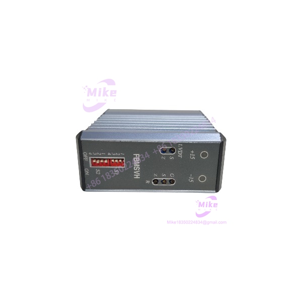
Description
Foxboro FBMSVH | LVDT Servo Valve Control Card
Product Introduction
A conventional analog output card tells a field device what signal to receive. FBMSVH closes the loop.
Foxboro FBMSVH is a specialized servo-control card designed for pneumatic or hydraulic servo-valve applications where the control system needs actual position feedback rather than an open-loop command. The available technical documentation identifies 4–20mA and 0–10VDC command inputs, LVDT feedback, internal LVDT modulation/demodulation, and a bidirectional servo-valve drive output.
That makes FBMSVH fundamentally different from a general-purpose Foxboro analog-output FBM. The card processes the commanded position together with LVDT feedback and applies configurable P or P+I control before generating the servo drive current.
For procurement, this distinction is critical. A generic 4–20mA output module may be electrically capable of transmitting a command, but it does not automatically reproduce the closed-loop servo-control function of FBMSVH.

FBMSVH
Key Technical Specifications
- Model: FBMSVH
- Manufacturer: Foxboro
- Application: Hydraulic and pneumatic servo-valve position control
- Command input 1: 4–20mA
- Command input impedance: approximately 500Ω, according to secondary technical documentation
- Command input 2: 0–10VDC
- Voltage input impedance: approximately 4.3kΩ
- Feedback: LVDT
- Reported LVDT feedback range: 0–10V signal
- LVDT maximum reported input: 18Vpp
- Servo output: ±27mA
- Reported maximum servo output: ±30mA
- Servo output load: approximately 80Ω
- Position feedback output: 0–20mA
- Position output impedance: approximately 50Ω
- Control algorithm: P or P+I
- Gain: Adjustable
- Integration time: Adjustable
- External supply: ±15VDC
- Typical external supply current: approximately 250mA per rail
- LVDT drive current: approximately 50mA
- LVDT oscillator frequency: 1kHz ±10%
- Operating temperature reported by secondary sources: 0°C to 50°C
- Storage temperature: -40°C to 70°C
The detailed electrical values above come from secondary technical sources rather than a currently published Schneider OEM datasheet, so they should be treated as procurement-verification specifications, not as permission to commission a replacement without checking the original plant documentation.
Closed-Loop Servo Architecture
The basic control chain is:
DCS command → FBMSVH → servo valve → actuator → LVDT feedback → FBMSVH
The command can be supplied as either 4–20mA or 0–10VDC. The LVDT provides position feedback, which the card demodulates and compares against the commanded position.
The control loop can use proportional control or proportional-plus-integral control. Gain and integration settings therefore matter directly to valve response, stability, and positioning accuracy.
This is not simply signal conversion.
An improperly configured gain value can produce slow response, oscillation, or unstable servo behavior even when every electrical connection is correct.
LVDT Interface
The LVDT section is one of the defining characteristics of FBMSVH.
The card provides excitation for the LVDT and processes the resulting feedback signal through an internal modulator/demodulator circuit. Secondary technical documentation reports a standard 1kHz excitation frequency and approximately 50mA LVDT drive current.
When troubleshooting an existing installation, verify:
- LVDT excitation
- Primary winding wiring
- Secondary winding wiring
- Sensor stroke
- Mechanical zero
- Feedback polarity
- Shield termination
- Cable routing
- Signal conditioning
- Valve mechanical linkage
Do not assume that two LVDTs with similar physical dimensions have identical electrical characteristics.
Servo Output
The reported FBMSVH servo output is bidirectional, unlike a conventional 4–20mA process output.
Secondary technical documentation specifies approximately:
- ±27mA operating output
- ±30mA maximum
- Approximately 80Ω load
- Dedicated servo-valve drive application
This output architecture allows the card to command the servo valve in both directions around the control zero point.
That is one of the fastest ways to distinguish FBMSVH from ordinary Foxboro analog-output hardware.
Position Feedback Output
FBMSVH also provides a reported 0–20mA valve-position output.
This can be used by the surrounding control system or monitoring architecture to represent the measured valve position independently of the servo drive current.
A practical commissioning check should therefore verify both:
- Servo drive current
- Position feedback current
If the servo output changes correctly but the position feedback remains fixed, the problem may be in the LVDT circuit, mechanical linkage, feedback scaling, or signal-conditioning path rather than the DCS command.
External Power Requirements
Secondary technical documentation identifies an external ±15VDC supply for FBMSVH and reports approximately 250mA per rail under the specified operating condition.
This needs to be checked before installation.
Do not substitute a generic single 24VDC supply simply because other Foxboro FBMs in the cabinet use 24VDC. The external power architecture is one of the defining electrical characteristics of this servo card.
Global Sourcing & Live-Test SOP
1. Inbound Verification
- Confirm the physical marking is FBMSVH.
- Photograph the OEM identification label.
- Record serial number and hardware revision if available.
- Compare connector arrangement with the removed card.
- Check for PCB corrosion, heat damage, and cracked components.
- Verify that the application is servo/LVDT control.
2. Electrical Inspection
Inspect:
- Field connector pins
- Backplane connector
- LVDT interface
- Servo output terminals
- External power connections
- Adjustment potentiometers
- PCB solder joints
- Signs of overheating
- Contamination or oxidation
Do not power an unknown surplus card immediately after unpacking if there is evidence of moisture exposure.
3. Bench Simulation
A proper functional test should use a compatible Foxboro test environment or an approved standalone simulation setup.
Recommended checks include:
- ±15VDC power acceptance
- Command input at 4mA
- Command input at 12mA
- Command input at 20mA
- 0–10V command response
- LVDT excitation
- Simulated LVDT feedback
- Servo output current
- Position feedback output
- Gain adjustment
- Integral response
- Shutdown input, if applicable
A calibrated multimeter/current meter should be used for current measurements. An LVDT simulator is preferable for complete functional verification.





