

Description
Foxboro FBMSSW | I/A Series Servo Control Module
Product Introduction
FBMSSW is not a conventional Foxboro analog input or discrete I/O module. Available technical listings identify it as a specialized servo-control card intended for applications involving servo valves and LVDT position feedback. That makes correct identification especially important when sourcing a legacy spare: replacing it with a general-purpose FBM201, FBM204, or FBM237 is not a functional substitute.
The available documentation consistently associates FBMSSW with servo applications, while one supplier specifically describes the function as “MOTOR SERVO.” Another technical listing identifies LVDT feedback processing, a 1 kHz excitation circuit, ±21 mA servo output, and ±15 VDC auxiliary power. These detailed electrical figures should nevertheless be treated as supplier-reported specifications pending confirmation against the installed Foxboro documentation, because I could not locate a current Schneider technical datasheet dedicated to FBMSSW.
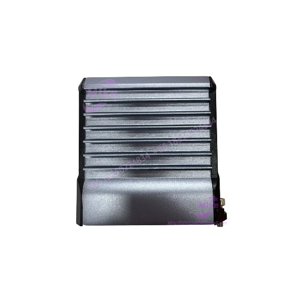
FBMSSW
Key Technical Specifications
- Model: FBMSSW
- Manufacturer: Foxboro / Invensys
- System: I/A Series DCS
- Product category: Specialized servo-control card
- Application: Electro-hydraulic / servo valve control
- Feedback type: LVDT
- Reported LVDT excitation frequency: 1 kHz
- Reported servo output: ±21 mA
- Reported auxiliary power: ±15 VDC external supply
- Communication architecture: Foxboro I/A Series Fieldbus environment
- Installation: Foxboro FBM-compatible control hardware
- Lifecycle: Legacy hardware; verify availability and revision before procurement
FBMSSW Functional Architecture
A conventional analog output module simply generates a commanded current. FBMSSW is intended for a different control problem.
In a servo-valve application, the control system needs both an actuator command and feedback representing actual mechanical position. An LVDT provides the position feedback, while the servo-control circuitry processes that feedback against the control demand and drives the associated valve actuator.
That closed-loop architecture is why a generic 4–20 mA output module should not automatically be considered an FBMSSW replacement.
For maintenance engineers, the practical distinction is straightforward:
- General analog I/O → signal acquisition or output
- FBMSSW → specialized servo-control application
- LVDT interface → mechanical position feedback
- Servo output → actuator/valve control current
Supplier documentation specifically describes FBMSSW as an LVDT servo valve control module and reports ±21 mA servo drive capability.
LVDT Feedback Considerations
LVDT systems are sensitive to wiring, excitation, shielding, grounding, and signal-conditioning configuration.
Before replacing an FBMSSW, verify:
- Installed LVDT sensor type
- Primary/secondary winding connections
- Excitation requirements
- Feedback scaling
- Valve stroke range
- Servo coil characteristics
- Field cable shielding
- Cabinet grounding arrangement
- Existing loop gain and bias settings
- Controller-side configuration
Do not assume that an LVDT sensor from another actuator package can simply be connected because the connector appears mechanically compatible.
Servo Output Considerations
The reported FBMSSW servo output specification is ±21 mA. That figure is substantially different from the conventional unidirectional 0–20 mA or 4–20 mA architecture used by many Foxboro analog-output FBMs.
This is an important procurement discriminator.
If the existing actuator expects bidirectional servo current, substituting a conventional 4–20 mA output module changes the electrical control architecture and can prevent the actuator from reaching the required operating range.
The ±21 mA figure and related servo-control specifications come from secondary technical listings rather than a current Schneider datasheet, so they should be verified against the plant’s original Foxboro documentation before commissioning.
Global Sourcing & Live-Test SOP
1. Inbound Verification
- Verify the exact marking FBMSSW on the physical card.
- Photograph the OEM identification label before installation.
- Record serial number and hardware revision where available.
- Check connector condition and keying.
- Compare PCB revision against the failed unit.
- Confirm whether the application is servo/LVDT control rather than ordinary I/O.
2. Electrical Inspection
Inspect:
- Field connector pins
- Backplane connector
- PCB contamination
- Electrolytic capacitors
- Trim potentiometers
- DIP switches, if fitted
- Signs of overheating
- Damaged components
- Corrosion around field-interface circuitry
For surplus Foxboro hardware, cosmetic appearance is not a sufficient acceptance criterion.
3. Functional Test
A proper bench test should use an appropriate Foxboro-compatible test environment.
Recommended verification includes:
- Power-up behavior
- Fieldbus communication
- LVDT simulator connection
- Excitation verification
- Simulated position feedback
- Servo output current measurement
- Zero/bias verification
- Full-scale feedback response
- Closed-loop response under a suitable load simulator
A calibrated multimeter/current meter should be used for output-current verification. If an LVDT simulator is unavailable, do not claim a complete functional test.
4. Final Preparation
Record:
- Hardware revision
- Firmware/configuration information where accessible
- Test date
- Test equipment
- Measured servo output
- LVDT simulation range
- Pass/fail result
Package the board in ESD-safe material with adequate mechanical protection.





