


Description
Foxboro FBM218 P0917XV | 8-Channel HART Output Interface
Product Introduction
The Foxboro FBM218 is not simply an 8-channel analog output card. It combines conventional 4–20 mA output with HART communication and adds module-level redundancy when two FBM218 units are installed as a pair.
Each of the eight output channels is galvanically isolated and has its own HART FSK modem. A field device can therefore receive the analog control signal while the Foxboro DCS exchanges HART information over the same loop. Schneider specifies compatibility with HART Versions 5, 6, and 7 and a communication rate of 1200 baud.
The P0917XV designation needs separate attention. Schneider’s documentation identifies P0917XV as a PVC termination assembly for the FBM218, not as the electronics module. The older PSS 31H-2Z18 lists P0917XV alongside P0926EK/P0926SP as FBM218 termination options, while the May 2025 PSS 41H-2S218 identifies RH926SP as the current polyamide compression TA.
For procurement, therefore, FBM218 + P0917XV should be treated as a module/termination configuration rather than one single part number.
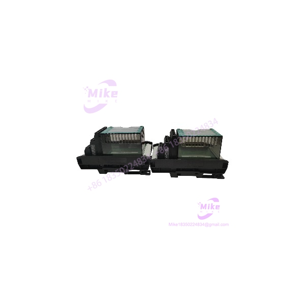
FBM218 P0917XV
Key Technical Specifications
Module
- Model:
- Current module part number: RH922VW
- Function: HART Communication Redundant Output Module
- Number of output channels: 8
- Output signal: 4–20 mA analog
- HART: FSK signal superimposed on 4–20 mA
- Supported HART versions: 5, 6, and 7
- HART communication: Point-to-point, master/slave, asynchronous, half-duplex
- HART speed: 1200 baud
- HART message rate: 2 messages per second
- HART burst mode: Not supported
- Output accuracy: ±0.05% of span between 4 and 20 mA
- Maximum output load: 750 Ω
- Output resolution: 13 bits
- Maximum output rate: 20 mA in 60 ms
- Channel isolation: Individual galvanic isolation
- Fieldbus: Redundant 2 Mbps HDLC Fieldbus
- Supply: 24 VDC +5% / -10%
- Maximum power consumption: 7 W
- Maximum heat dissipation: 5 W
- Operating temperature: -20 to +70°C (-4 to +158°F)
- Storage temperature: -40 to +70°C (-40 to +158°F)
- Humidity: 5–95%, noncondensing
- Environment: ISA S71.04 Class G3
- Vibration: 0.75 g, 5–500 Hz
- Weight: Approximately 284 g
- Dimensions: 102 × 45 × 104 mm
- Height with mounting lugs: 114 mm
- Termination cable length: Up to 30 m / 98 ft
These values are documented in Schneider Electric’s current PSS 41H-2S218, Rev C, May 2025.
P0917XV Termination Assembly
- Part number: P0917XV
- Application:
- Signal: 8 × 4–20 mA outputs, with optional HART signal
- Termination type: Compression
- Material: PVC
- TA cable type: Type 1
- Certification type: Type 1 / Type 2 configurations documented
- Field connection: Compression screw terminals
- Cable length: Up to 30 m
- Cable materials: Polyurethane or LSZH
The older Schneider PSS 31H-2Z18 explicitly lists as an TA.
HART Output Architecture
The provides eight isolated current-output channels. Each channel can generate a conventional 4–20 mA signal, while HART FSK communication can be superimposed on that current loop.
The module includes a dedicated FSK modem for each output channel. This allows the Foxboro DCS to communicate with an intelligent field device without requiring a separate HART multiplexer.
The documented HART communication path supports universal, common-practice, and device-specific commands. However, HART burst communication is not supported. That distinction matters when integrating smart valves, positioners, or other HART actuators whose communication behavior has already been configured in the field.
Redundant Analog Output Operation
The is designed around module-level output redundancy.
Two modules are installed in adjacent baseplate positions. One operates as the Master and the other as the Tracker, with both connected to the same field output termination through a redundant adapter.
If one module is detected as failed, its affected output is driven to 0 mA and the corresponding channel on the healthy module continues supplying the required loop current. Schneider provides configurable fail-safe parameters for output behavior, including Hold/Fallback, fallback data, Fieldbus fail-safe enable, and Fieldbus fail-safe delay.
This architecture is useful for control valves and other final control elements where loss of a single I/O module should not automatically interrupt the process.
Individual Channel Isolation
All eight output channels are galvanically isolated from one another and from ground and module logic.
The isolation uses both optical and transformer isolation. Schneider specifies a 600 VAC, one-minute withstand test between isolated channels and ground.
That 600 VAC figure is not a continuous operating-voltage rating.
The published safety warning explicitly states that the channels are not intended for permanent connection to hazardous-voltage circuits. Do not use the dielectric withstand specification as permission to connect an output to an arbitrary high-voltage circuit.
Output Performance
The produces a 0–20 mA internal output range while the specified analog accuracy is given for the normal 4–20 mA span.
Key performance figures include:
- ±0.05% span analog accuracy
- 13-bit resolution
- 750 Ω maximum load
- 20 mA change within 60 ms maximum rate specification
The module’s output circuitry is current-limited and voltage-regulated. Schneider states that normal operation provides constant current into a 0–750 Ω load.
When engineering a control-valve loop, calculate the complete compliance-voltage budget instead of checking only the FBM output specification. Cable resistance, valve positioner input resistance, intrinsic-safety barriers, and other series devices can consume a significant portion of the available loop voltage.
Termination Assembly
The is the field termination interface associated with the older architecture.
Schneider’s PSS 31H-2Z18 identifies the termination assemblies as DIN-rail-mounted and electrically passive. The is the PVC version with compression terminals.
The termination cable is removable, allowing the TA to be installed either inside the primary enclosure or in an adjacent enclosure. Cable lengths are available up to 30 m.
The older documentation identifies , P0926EK, and P0926SP in the TA configuration. The May 2025 specification has moved to RH926SP for the current polyamide compression TA.
This is important when sourcing legacy Foxboro hardware: should not automatically be advertised as the current OEM TA part number.
Fieldbus Communication
The communicates with its associated Fieldbus Communication Module or Field Control Processor through a redundant 2 Mbps HDLC Fieldbus.
Both Fieldbus paths A and B are supported. If one communication path becomes unsuccessful or is switched at the system level, the continues through the active path.
For troubleshooting, separate the system into three layers:
- Controller command generation
- analog/HART output processing
- Field-device loop and final-element response
A correct 4–20 mA measurement at the field device does not automatically prove that HART communication or controller-side configuration is correct.
Mechanical Installation
The standard mounts on a modular 200 Series baseplate.
The baseplate can be installed:
- Horizontally on DIN rail
- Vertically on DIN rail
- Horizontally in a 19-inch rack with the appropriate mounting kit
For redundant operation, the two modules must occupy adjacent baseplate positions: 1/2, 3/4, 5/6, or 7/8. A redundant adapter connects the two module termination interfaces to a single termination cable and TA.
The current redundant adapter is RH916QD.
Global Sourcing & Live-Test SOP
1. Inbound Verification
For an / procurement lot:
- Verify the module front-panel designation as .
- Record the module hardware identifier.
- Distinguish the module part number from the TA part number.
- If the module is marked P0922VW or RH922VW, document the exact revision.
- Verify as the supplied termination assembly where applicable.
- Inspect the D-sub connectors and baseplate interface.
- Check the TA terminal blocks for corrosion or deformation.
- Record serial number and visible hardware revision.
- Inspect labels for relabeling or counterfeit indicators.
- Trace available OEM paperwork and historical configuration information.
2. Live Simulation
Recommended acceptance testing should verify representative output values:
- 4 mA
- 12 mA
- 20 mA
Test several channels simultaneously.
For HART applications, connect an appropriate HART-capable test device and verify:
- Analog current
- HART device identification
- HART command exchange
- Digital communication stability
A calibrated current meter can verify the analog loop, but it does not prove successful HART communication.
3. Redundancy Test
For a redundant pair:
- Verify Master/Tracker status.
- Confirm both modules communicate over the Fieldbus.
- Apply representative output commands.
- Confirm the healthy module maintains the field output when the other module is removed under the approved maintenance procedure.
- Verify the failed-side output behavior.
- Confirm controller diagnostics identify the correct module status.
The actual maintenance test should be performed only under the site’s approved DCS procedure.
4. Final Preparation
Record:
- module part number
- TA identification
- Hardware revision
- Firmware information where available
- Serial number
- Test results
- HART communication result
- Redundancy test result, if performed
Use ESD-safe packaging and protect both the module connector and TA terminals during shipment.
A 24-hour heat run can be added to a critical-spare acceptance program, but it should only be described as completed when actual test documentation exists.
Field Engineer’s Pitfall Guide
❗ Do not list as the electronics part number.
is the termination assembly. The older electronics part number is P0922VW, while the current Schneider specification identifies RH922VW. Mixing these identifiers can cause the wrong item to be quoted or shipped.
❗ Do not assume is the current TA designation.
Schneider’s current May 2025 specification identifies RH926SP as the current polyamide compression TA and notes the newer hardware lineage. appears in the older specification as the PVC TA. Verify the installed cabinet before substituting.
❗ Do not verify a redundant only by checking the process output.
The redundancy mechanism depends on Master/Tracker status, redundant adapter wiring, Fieldbus communication, fail-safe configuration, and the controller database. A stable output alone does not prove that module redundancy is functioning correctly.





