

Description
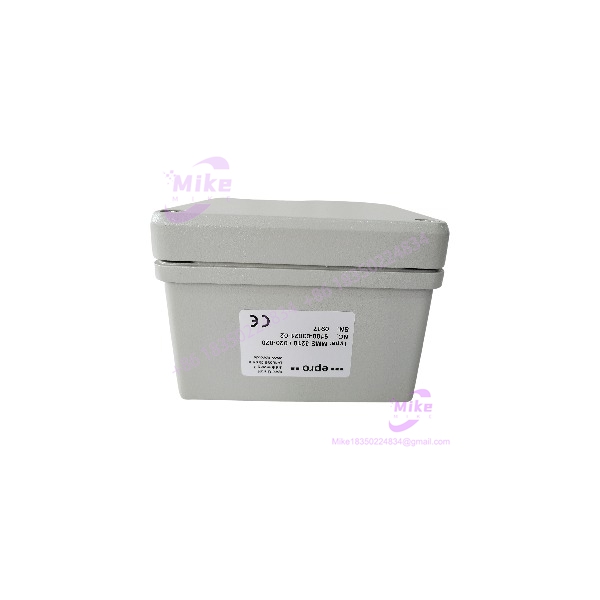
EPRO MMS3210/020-020 | Dual-Channel Shaft Monitor
Product Introduction
The EPRO MMS3210/020-020 is a two-channel transmitter used with eddy-current proximity sensing on rotating machinery. Its role is to take conditioned shaft-position or shaft-vibration information and convert it into standardized monitoring signals for a plant DCS, PLC, machinery-protection system, or local monitoring architecture.
This is a field-replacement part where the sensor chain matters. The MMS3210 family is designed around EPRO PR 642x eddy-current sensors, and the transmitter architecture provides independent processing of two measurement channels. Depending on configuration, the outputs can represent each channel separately or a selected combined value — useful in machinery-protection schemes where the highest of two measurements is the value that must reach the control system.
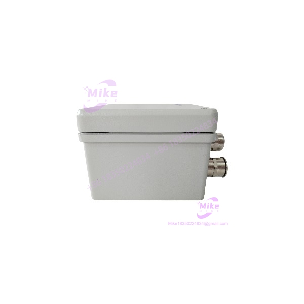
MMS3210/020-020
Key Technical Specifications
- Model: EPRO MMS3210/020-020
- Alternate inventory format: MMS3210020-020
- System family: MMS 3000
- Measurement architecture: Dual-channel
- Input technology: Eddy-current displacement/proximity sensors
- Supported probe families: PR 6422, PR 6423, PR 6424, PR 6425, and PR 6426
- Measurement applications: Shaft relative displacement, shaft position, radial displacement/vibration, and related turbomachinery measurements depending on configuration.
- Input channels: 2 independent sensor channels
- Analog outputs: 2 × 0/4–20 mA in the documented dual-output arrangement
- Output behavior: Current output proportional to the corresponding measurement
- Combined-output capability: Configuration can provide a value proportional to the maximum of two channels where required by the application.
- Output load: The MMS3210 family documentation identifies a maximum current-loop load of approximately 500 Ω for its 0/4–20 mA outputs.
- Buffered test outputs: The MMS3210 family provides buffered voltage outputs for testing/diagnostic purposes in applicable configurations.
- OK monitoring: Integrated monitoring checks the sensor/transmitter condition.
- Fault behavior: The documented architecture changes the OK status and drives the affected current output toward 0 mA when a monitored fault is detected.
- Limit supervision: Configurable measurement-limit monitoring is available within the architecture.
- Sensor fault monitoring: Open/short sensor and associated circuit faults can be supervised.
- Frequency response: Configuration-dependent; do not assume a generic bandwidth for every suffix.
- Configuration: Hardware/configuration settings determine the measurement mode and output behavior.
- Supply: The family uses 24 VDC-class industrial power; verify the exact nameplate and wiring configuration on the /020-020 before energizing a replacement.
- Mounting: MMS 3000 transmitter architecture supports installation close to the machine as well as system integration arrangements.
- Standards/application: Associated with API 670 machinery-protection applications.
- Typical machinery: Steam turbines, gas turbines, compressors, pumps, fans, blowers, gearboxes, centrifuges, and other rotating equipment.
- System integration: Designed for connection to PLC, DCS, protection, and machinery-monitoring systems.
Application Scenarios & Pain Points
Shaft Displacement Monitoring
The family is commonly applied where an eddy-current probe measures the relative position of a rotating shaft. Typical examples include axial position, thrust position, thermal expansion, or radial shaft movement.
For these applications, the transmitter’s job is not simply to provide a number. It must preserve the probe’s calibrated relationship to shaft position while providing a usable signal to the protection or control system.
Dual-Probe Machinery Protection
Two independent probes can be processed as separate channels. In protection architectures where the greater of two measurements is required, the family can be configured for maximum-value processing rather than forcing the DCS to perform that calculation externally.
Turbine and Compressor Applications
Large rotating machines frequently use several eddy-current probes around the shaft train. The architecture supports applications involving turbines, compressors, pumps, fans, gearboxes, centrifuges, and similar equipment.
Legacy MMS 3000 Replacement
A physically similar MMS transmitter is not automatically an electrical equivalent. The replacement has to match the probe family, measurement range, output configuration, alarm logic, and existing plant scaling.
That is especially important when the original installation has been operating for years and the DCS database contains engineering-unit scaling that nobody wants to disturb during a maintenance window.
DCS / PLC Analog Integration
The 0/4–20 mA architecture makes the transmitter suitable for conventional analog-input systems. The receiving channel still needs to be checked carefully: zero point, full-scale displacement, alarm thresholds, fault-current interpretation, and loop resistance all matter.
QA & Live Testing SOP
For an incoming , test the measurement chain rather than stopping at a basic power-up.
- Visual inspection: Check the enclosure, PCB, terminals, connectors, adjustment hardware, and mounting points for damage, corrosion, contamination, or unauthorized rework.
- Nameplate verification: Confirm the complete designation before connecting power.
- Power test: Apply a controlled 24 VDC-class supply within the verified specification for the exact unit.
- Channel 1 test: Connect a known-good compatible eddy-current sensor simulator and verify the measurement response.
- Channel 2 test: Repeat independently. One passing channel does not establish that the second signal path is healthy.
- Gap/position simulation: For displacement applications, use a controlled input representing known probe gap or displacement values.
- Current-loop test: Verify the corresponding 0/4–20 mA output against several known input points.
- Output linearity: Check low, mid-scale, and high-scale points rather than validating only zero and full scale.
- Maximum-value mode: If the application uses combined two-channel processing, verify the maximum-value behavior with unequal Channel 1 and Channel 2 inputs.
- OK-status test: Introduce a controlled sensor/input fault and verify the expected OK-status response.
- Alarm test: Exercise configured limit thresholds and confirm the corresponding status/alarm output.
- DCS simulation: Verify that the receiving analog-input channel interprets the transmitter’s fault state correctly instead of displaying a false zero measurement.
- ESD handling: Use ESD-safe packaging and protect the sensor/terminal connections during storage and shipment.
A serious acceptance test should therefore follow:
Eddy-current probe → /020-020 → signal processing → 0/4–20 mA output → PLC/DCS/protection input.
Field Engineer’s Pitfall Guide
❗ Do not confuse /020-020 with /022-000. Both belong to the family, but the complete suffix identifies the configuration. The documented is a dual-channel shaft-position transmitter with PR 642x sensor inputs; do not assume its exact output and configuration options are identical to .
❗ Verify the exact probe type and measurement range. PR 6422 through PR 6426 sensors cover different physical measurement ranges. A transmitter configured for one probe range cannot simply be paired with another probe because both use the same general eddy-current technology.
❗ Check the DCS fault interpretation. In the documented architecture, a detected fault can force the current output toward 0 mA while changing the OK status. If the DCS interprets 0 mA as a genuine minimum process value instead of a transmitter fault, the plant alarm logic can become misleading.
❗ Do not change probe gap during transmitter replacement unless the calibration procedure requires it. The probe’s mechanical gap and linearization are part of the measurement chain. Changing the physical gap can alter the signal even when the transmitter itself is functioning correctly.
❗ Verify whether the plant uses independent or maximum-value outputs. Two-channel monitoring can be configured around separate channel outputs or combined maximum-value processing. Confirm the existing application before rewiring the replacement.
Intent-Driven FAQ
Q: What is the EPRO /020-020?
A: The is a dual-channel MMS 3000 transmitter designed to process eddy-current sensor signals for rotating-machinery shaft monitoring.
Q: What sensors work with /020-020?
A: The family is designed around EPRO PR 6422, PR 6423, PR 6424, PR 6425, and PR 6426 eddy-current sensor families, with the exact probe and measurement range matched to the transmitter configuration.
Q: Is /020-020 a vibration monitor or a displacement transmitter?
A: Its application depends on the configured measurement function. The architecture processes relative shaft-position/displacement signals and can be used for radial shaft vibration/displacement-related measurements. The exact configuration should be checked before assigning a specific engineering-unit range.
Q: How many channels does /020-020 have?
A: Two independent measurement channels.
Q: Does /020-020 provide 4–20 mA outputs?
A: Yes. The documented architecture provides 0/4–20 mA proportional current outputs, with the exact output configuration depending on the ordered variant.
Q: Can two channels be combined?
A: The architecture supports a configuration in which one output represents the maximum value of the two channels, in addition to independent-channel operation. Confirm that this function is present and configured on the specific unit before commissioning.
Q: Does /020-020 have sensor fault detection?
A: Yes. The architecture includes an OK/self-check function that monitors the transmitter and sensor circuit. A detected fault changes the OK state and can alter the analog output behavior.
Q: Is /020-020 a direct replacement for /022-000?
A: Do not treat the two suffixes as automatically interchangeable. Compare the sensor interface, measurement range, output arrangement, alarm configuration, and plant wiring before approving a substitution.
Q: What should be verified before purchasing MMS3210020-020?
A: Confirm the complete designation, installed PR 642x probe, probe measurement range, required shaft measurement function, current-output scaling, alarm/OK behavior, power wiring, and existing DCS/PLC configuration. For legacy turbomachinery, matching the complete measurement chain is more important than matching the enclosure or base model alone.





