

Description
Westinghouse 1C31125G01 | Direct Replacement 16-Ch Output Base Unit
Product Introduction
When a digital output loop fails in an Ovation rack, replacing the top processing card only solves half the problem. The Emerson 1C31125G01 is not a simple terminal connector; it is the physical and electrical Personality Module (PMOD) designed specifically to pair with the 1C31122G01 Digital Output Electronics Module (EMOD) on standard Ovation I/O bases. Snapping directly into the lower slot of the base unit, it handles raw field-wiring landings, individual line isolation, and local short-circuit protection for up to 16 single-ended 0–60 VDC output loops.
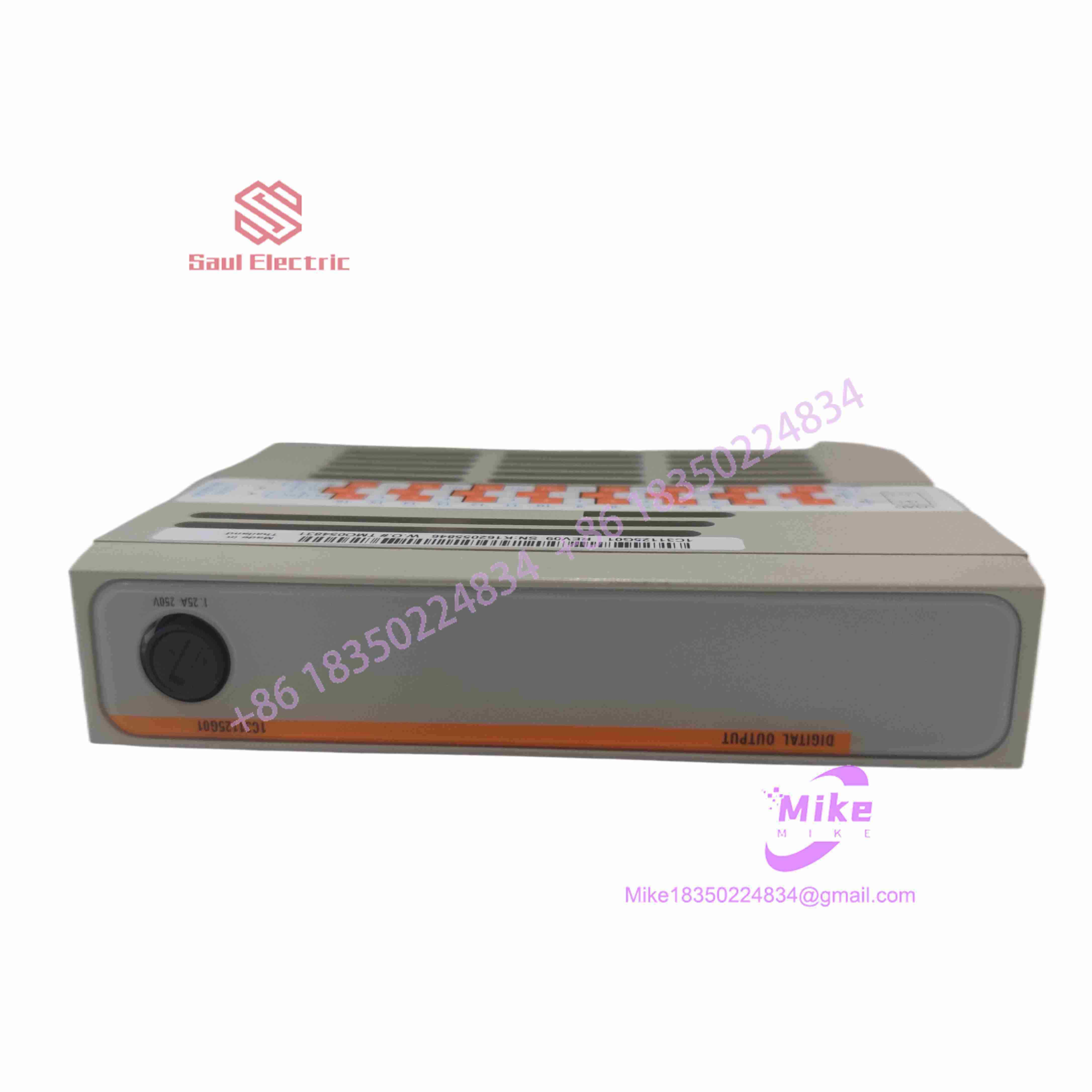
1C31125G01

1C31125G01
Field devices like pilot solenoid valves, interposer relay coils, and alarm beacons draw real power and generate inductive kickback that can easily wipe out delicate microprocessor logic. The 1C31125G01 shields your controller bus by enforcing a strict 1000V AC/DC galvanic isolation barrier between field power and logic planes. Featuring onboard fuse detection circuitry that feeds status bit registers directly to the controller, this module ensures that a blown field fuse triggers an immediate diagnostic alarm on the HMI—long before a tripped valve halts your entire boiler feed sequence.
Key Technical Specifications
| Parameter | Technical Specification |
| OEM Part Number | 1C31125G01 |
| System Family | Emerson / Westinghouse Ovation DCS |
| Module Type | Digital Output Personality Module (PMOD) |
| Paired Electronics Module | Emerson 1C31122G01 (DO EMOD) |
| Channel Count | 16 single-ended channels |
| Load Voltage Range | 0 to 60 VDC |
| Max Current per Channel | 500 mA continuous |
| Total Current Group Limit | 890 mA (Group 1) / 2.2 A (Group 2/3 with relay panel) |
| Isolation Rating | 1000 V AC/DC (channels to system logic) |
| Propagation Delay | Max 2.5 ms (R_{load} = 500\,\Omega) |
| Status LEDs | P (Power), C (Comms), E (External Error), I (Internal Error), CH1–CH16 |
| Operating Temperature | 0°C to +60°C (32°F to +140°F) |
Application Scenarios & Pain Points
Scenario 1: Field Diary – Water Treatment Dosing Skid
An industrial water treatment plant in North Carolina suffered from mysterious, unflagged digital output failures that left chemical injection valves closed during high-demand cycles. The technician swapped the top EMOD card twice, but the outputs remained dead. The real issue was a blown micro-fuse on an aging personality module caused by a shorted solenoid coil. Swapping in a fresh 1C31125G01 cleared the external error flag (E LED) and restored full diagnostic visibility to the main control drop in under 10 minutes.
Scenario 2: With vs. Without Dedicated PMOD Modules
- Without 1C31125G01: Field power wiring lands directly on sensitive card headers. Inductive spikes from unsuppressed DC relay coils pass directly into processing logic, causing system bus resets, random card trips, or permanent hardware damage.
- With 1C31125G01: Field-side energy stays isolated on the base assembly. Standard field-wiring terminals, onboard fuse monitoring, and galvanic isolation protect the top-level processing card while keeping maintenance simple.
Scenario 3: High-Reliability Operations
- Relay Panel Interfacing: Interfacing with solid-state or G2R electromechanical relay panels for higher current switching needs. The 1C31125G01 acts as the clean intermediate driver module, passing signals safely without over-stressing the cabinet bus.
- Configurable Fail-Safe Environments: Applications where outputs must behave predictably during a controller communication drop. The module’s timeout register can be configured (62 ms to 16 s) to hold last state or force outputs to a safe OFF state automatically.
QA & Live Testing SOP (Trust Signal)
Every 1C31125G01 personality module undergoes rigorous multi-step testing before being certified for field installation:
- Physical & Terminal Inspection: We verify all edge-connector contacts, fuse holders, and base retention latches under high magnification to rule out hairline PCB fractures or contact oxidation.
- Fuse Detection & Diagnostic Check: We deliberately blow a test fuse on the board to confirm that the diagnostic circuit correctly trips Bit 6 in the status register and lights the faceplate External Error (
E) LED. - High-Voltage Isolation & Resistance Test: We put the unit on a Fluke insulation tester to verify a full 1000V AC/DC isolation barrier between field terminal pins and backplane logic paths.
- Live Rack Handshake: The PMOD is seated into an active Ovation base beneath a functional 1C31122G01 EMOD card. We drive 24 VDC loads across all 16 channels simultaneously to verify zero channel-to-channel cross-talk and sub-2.5 ms propagation speed.
- Anti-Static Packaging: Cleared units are sealed in heavy ESD shielding bags and shipped in custom-molded foam boxes.
Field Engineer’s Pitfall Guide
❗ WARNING 1: Mind Total Group Current Limits
While each individual channel supports up to 500 mA, you cannot run all 16 channels at 500 mA at the same time. Total current across Group 1 is strictly capped at 890 mA. Exceeding group thermal ratings will trip internal board protection or blow the primary supply fuse!
❗ WARNING 2: Land Shield Wires Correctly for CE Compliance
When switching DC voltages above 30 V RMS in CE-compliant installations, use braided shielded field cables. The cable shield must be grounded directly at the cabinet entrance point, and a warning label (part number 1B30025H01) must be affixed to the base assembly.
❗ WARNING 3: Never Pull the PMOD Under Live Field Power
Although Ovation top-level EMOD cards support hot-swapping, pulling the 1C31125G01 personality module while field power is applied to the terminal block will cause electrical arcing across the base pins and can trip upstream 24 VDC power supplies.
Intent-Driven FAQ
Q: Do I need to buy the 1C31122G01 module separately?
A: Yes. The 1C31125G01 is the Personality Module (PMOD) that sits on the lower portion of the Ovation I/O base. It requires the upper Electronic Module (EMOD—part number 1C31122G01) to process digital commands from the controller drop.
Q: What does a steady red External Error (E) light mean on this module?
A: The red E LED indicates an external field-side fault—most commonly a blown channel fuse or a complete loss of the external 24/48 VDC field power supply (PS+ / PS-) wired to the terminal block.
Q: Can I use the 1C31125G01 to switch 120 VAC lighting or solenoid circuits?
A: No. The 1C31125G01 is strictly rated for 0 to 60 VDC loads. If you need to switch 120 VAC or higher AC loads, you must route the 1C31125G01 outputs into an intermediate electromechanical or solid-state interposer relay panel.
Q: What happens to the outputs if communication with the controller fails?
A: The module features a configurable communication timeout register (selectable from 62 ms to 16 s). Depending on how your software drop is configured, the 1C31125G01 will either hold its last state or force all 16 channels to a de-energized (OFF) state upon timeout.
Q: What warranty is included with this surplus/refurbished unit?
A: Every 1C31125G01 module comes backed by our comprehensive 12-month full replacement warranty. If a channel fails or a diagnostic fault occurs during setup, we will swap it immediately from our emergency warehouse inventory.





