Description
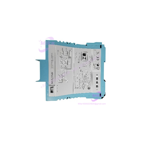
Eaton MTL5549 | 2-Channel Isolating Driver, 4-20mA HART
Architect’s Product Breakdown
The Eaton MTL5549 operates as a dual-channel isolating driver engineered to power and control 4-20mA smart field instruments—such as valve positioners and current-to-pressure (I/P) converters—situated in explosive hazardous zones. Belonging to the widely adopted MTL5500 DIN rail product family, this model provides complete galvanic isolation between the safe-area control system and hazardous-area field devices while supporting transparent, bidirectional digital HART communication overlay and integrated line fault detection.
Deploying this hardware requires careful planning regarding cabinet layout, power distribution rails, and loop resistance boundaries. Because the module mounts onto standard 35 mm DIN rail carriers, thermal dissipation and proper spacing between adjacent units must be maintained to prevent internal overheating under continuous high-current loops. System integrators must also verify that safe-area control output cards match the sinking or sourcing configuration required by the driver terminals.
MTL5549
Key Technical Specifications
| Parameter | Specification |
| Model Designation | MTL5549 |
| Number of Channels | Two independent channels |
| Supply Voltage | 20 V to 35 V DC |
| Current Consumption | 95 mA typical at 24 V DC (with 20mA loops) |
| Input Signal | 4 to 20 mA from safe-area controller |
| Hazardous-Area Output | 4 to 20 mA for smart instruments (Zone 0, 1, or 2) |
| HART Communication | Bidirectional pass-through (500 Hz to 10 kHz) |
| Line Fault Detection (LFD) | Open and short-circuit detection via transistor output |
| Power Dissipation | 2.2 W typical at 24 V DC |
| Ambient Operating Temperature | -20°C to +60°C |
| Mounting Style | 35 mm DIN Rail |
Field Engineer’s Pitfall Guide
- WARNING: Total Loop Resistance Limits. Never exceed the maximum load resistance threshold specified for the output loop. I once spent an entire afternoon debugging a sluggish valve positioner response on an MTL5549 loop, only to discover that excessive cable length pushed total resistance past the driving capacity limit, distorting the HART signal overlay.
- WARNING: Power Rail Voltage Sag. Ensure the bulk 24V DC power supply feeding the DIN rail does not sag under heavy transient loads when multiple driver channels modulate simultaneously. Voltage drops will cause communication timeouts and erratic analog output behavior.
- WARNING: Sinking vs. Sourcing Mismatch. Double-check safe-area controller output card wiring. Reversing polarity between active and passive terminal connections will block current flow and force field actuators to zero position.
QA & Testing SOP
- Visual & Origin Verification: Inspect the outer polyamide enclosure for structural cracks, verify OEM laser tracking marks, and check terminal block contacts for oxidation.
- Power-Rail Bench Test: Mount the module onto an active DIN rail test rig powered by a regulated 24V DC supply to confirm stable green power LED illumination.
- Current Loop Calibration: Inject a 4mA to 20mA signal into the safe-area input terminals via a process calibrator and measure hazardous-side output current to ensure strict linearity.
- HART Pass-Through & LFD Verification: Test bidirectional digital communication packet integrity across both channels and induce open/short faults to validate correct LFD transistor state transitions.
- Packaging: Seal in an anti-static moisture-barrier bag and pack with dense foam cushioning inside an exterior shipping box.
Technical FAQ
Can I hot-swap this isolating driver module while the panel power is active?
DIN-rail mounted units like the MTL5549 generally require isolating power before disconnecting terminal blocks, unless specific pluggable connector configurations and plant live-maintenance policies permit otherwise.
Does this module supply power to the field instrument?
Yes. It acts as an isolating driver that energizes the 4-20mA loop for smart positioners and I/P converters deployed in the hazardous area.
Can I use the MTL5549 for single-channel applications or must both channels be wired?
You do not need to populate both channels; unused channels can safely remain open without affecting the operation of the active loop.
What is the primary difference between the standard and variants like the MTL5549C or MTL5549Y?
The standard features full open-circuit and short-circuit line fault detection, whereas the C and Y suffix models tailor the line fault detection thresholds and behaviors (such as open-circuit only or specific fault current drops) to match exact DCS requirements.