


Description
B&R 8V1010.00-2 | Factory Sealed In-Stock Drive
Dynamic Product Introduction
The 8V1010.00-2 is B&R’s compact entry point into the ACOPOS 1010 servo drive family. Designed to drive smaller synchronous motors in packaging, labeling, and pick-and-place systems, this drive integrates direct mains power conversion, DC bus management, and fast current control loops into a single space-saving housing.
Operating at 3\times 400–480 VAC mains input, the unit delivers 2.2 A of continuous output current with short-duration peak current capacity up to 4.4 A for rapid acceleration ramps. The front panel features modular plug-in slots for pluggable interface cards (such as POWERLINK AC114, CANopen AC110, or resolver cards like AC122/AC123), allowing flexible integration into standard Automation Studio control trees without replacing the base drive hardware.
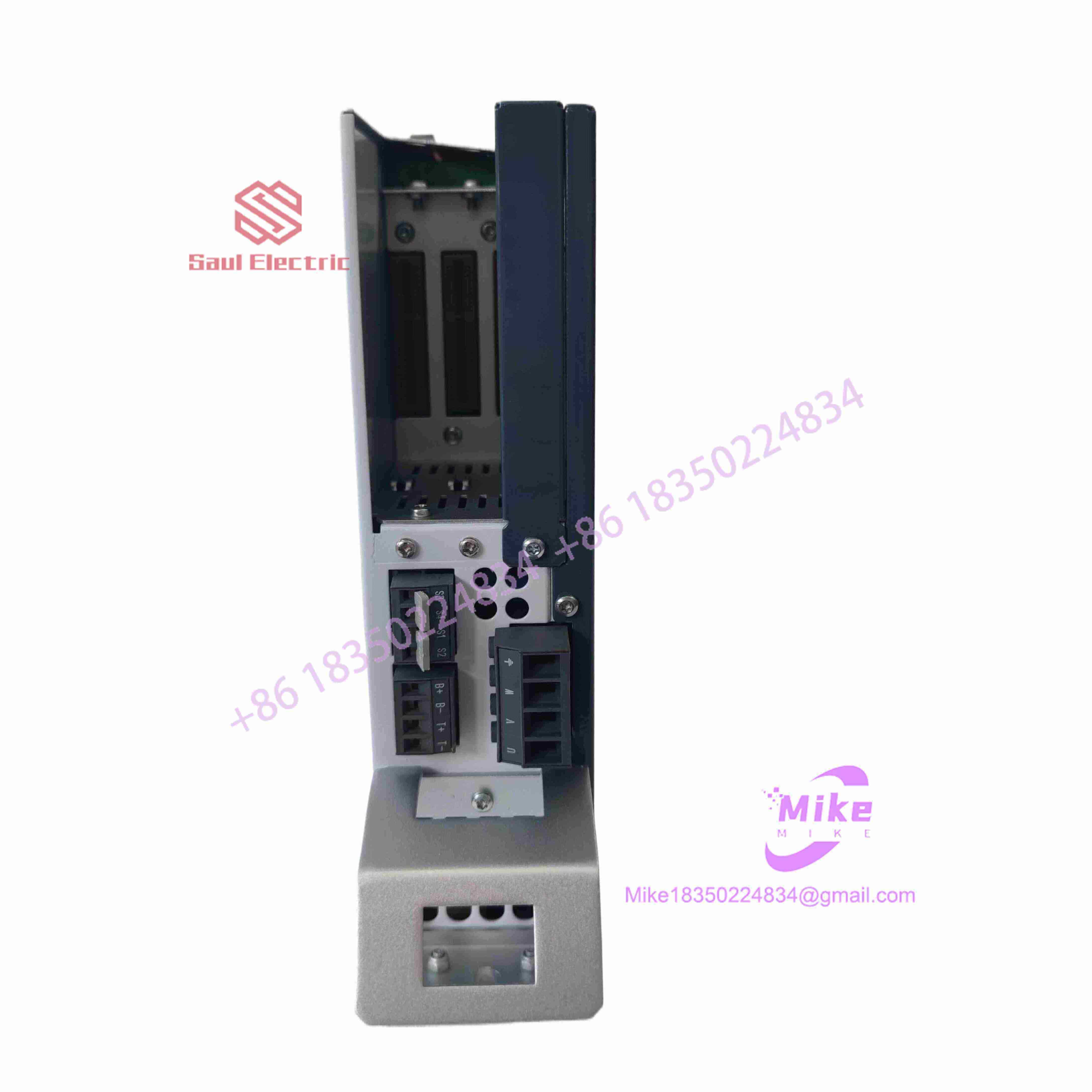
8V1010.00-2
Key Technical Specifications
| Parameter | Specification | Field Note / Operational Limit |
| Mains Input Voltage | 3\times 400 VAC to 480 VAC (\pm 10\%) | 50/60 Hz supply line connection |
| Continuous Current (I_N) | 2.2 A RMS | Nominal continuous current output at 8 kHz switching |
| Peak Current (I_{\max}) | 4.4 A RMS | Peak dynamic current capacity (up to 5 seconds) |
| Power Consumption | ~1.8 kVA | Apparent output power rating |
| 24V Control Power | 24 VDC (\pm 15\%) | External logic supply input required for control electronics |
| DC Bus Voltage | 560–800 VDC | Internal DC bus link created from rectified mains |
| Option Slots | 3 Expansion Card Slots | Accommodates network cards (POWERLINK, CAN) & feedback cards (Resolver, EnDat) |
| Braking Resistor | Integrated / External Terminals | Internal braking resistor built-in with connections for external heavy-duty resistors |
| Cooling Method | Integrated Fan Heatsink | Forced cooling; requires minimum 100mm vertical clearance top/bottom |
Global Sourcing & Live-Test SOP (Transparency Core)
Replacing complex industrial servo drives requires comprehensive testing. An untested drive can fail under load due to degraded DC bus electrolytic capacitors or damaged IGBT output gates. Every unit undergoes strict quality validation before shipment:
- Inbound Visual & Component Check:
We inspect the housing, power terminals, and option card bus connectors. Internal electrolytic DC bus capacitors are tested for Equivalent Series Resistance (ESR) and capacitance drift.
- 24V Logic & Fieldbus Communication Test:
24 VDC logic power is applied to confirm CPU boot-up, status LED readiness, and communication handshake over plugged-in network cards (
AC114POWERLINK /AC110CANopen) in Automation Studio. - Full-Voltage Dynamic Motor Run:
The drive is powered with 400 VAC mains supply and connected to an 8MSA series servo motor under load. The unit runs a multi-hour dynamic trajectory profile to monitor:
- IGBT temperature stabilization under continuous current.
- PWM switching symmetry across all output phases (U, V, W).
- Regeneration braking circuit activation during rapid deceleration.
- ESD Packaging & Shipping:
Option card slot covers are secured, and main power plug terminals are checked. The drive is sealed in static-shielding bags and cradled in high-density foam packaging.
The Field Engineer’s Pitfall Guide
- ❗ Never Connect Mains Power Without 24V Logic Initialization:
Always ensure the 24 VDC logic power supply is connected and stable before applying 400/480 VAC mains power. Applying main line voltage to an ACOPOS drive without active control logic can trigger DC bus charging circuit faults or cause uncontrolled current surges through the pre-charge resistors.
- ❗ Discharge DC Bus Capacitors Before Servicing:
After removing mains supply power, the internal DC link capacitors retain lethal voltage (>700 VDC) for several minutes. Always measure the voltage across terminals
DC+andDC-with a calibrated multimeter and verify it has dropped below 50 VDC before touching wiring or swapping option cards. - ❗ Hot-Plugging Option Cards Damaging Internal Buses:
Never insert or remove plug-in option cards (e.g.,
AC114,AC122,AC130) while 24 VDC or main power is applied to the drive. Inserting cards on a live drive will burn out the internal backplane bus interface chips, rendering the card slot non-functional.
Intent-Driven FAQ
What is the difference between 8V1010.00-2 and larger drives like 8V1045.00-2?
The model numbers indicate current capacity within the ACOPOS 1000 family:
- 8V1010.00-2: Continuous current of 2.2 A RMS (smallest drive in the series).
- 8V1022.00-2: Continuous current of 4.4 A RMS.
- 8V1045.00-2: Continuous current of 8.8 A RMS.
Does the 8V1010.00-2 come with built-in motor feedback inputs?
No. Standard ACOPOS base drives use modular expansion slots. To read motor position feedback (resolver, EnDat, or incremental encoder), you must plug a corresponding feedback card—such as an AC122 (Resolver) or AC130 (EnDat)—into option slot 2 or 3.
Can I use this drive on a single-phase 230 VAC power supply?
No. The 8V1010.00-2 requires a three-phase 400–480 VAC mains supply to build the required DC link voltage (~560–700 VDC). Running on 230 VAC single-phase will result in persistent undervoltage faults (Undervoltage DC Bus Error 6019).
What does error code 6019 on an ACOPOS drive mean?
Error 6019 indicates a DC Bus Undervoltage condition. It typically occurs if main 400 VAC power drops out, an incoming main supply fuse has blown, or the internal pre-charge circuit relay fails to close.
How can I verify that a replacement 8V1010 drive is unused OEM stock?
Inspect the terminal block screws, mounting rail clips, and option card bus pins. Unused factory-sealed units show no torque wear on terminal screws, zero mounting scratch marks on the rear DIN-rail/backplate mounting flange, and pristine connector pins without insertion marks.





