


Description
B&R 8MSA2S.R0-K4 | ACOPOS Compatible Servo
Dynamic Product Introduction
Miniature high-speed axes in pick-and-place sorters frequently trip drive amplifiers due to rotor thermal saturation and high electrical time constants. B&R engineered the 8MSA2S.R0-K4 specifically to solve that dynamic bottleneck in tight machinery footprints. Housing high-coercivity NdFeB permanent magnets inside a compact Size 2 frame (~55mm flange), this motor maintains high angular acceleration up to 6000 RPM while keeping internal inertia down to fractions of a gram-centimeter squared.
In field retrofits, replacing worn micro-servos or third-party stepper drives with the 8MSA2S.R0-K4 brings noticeable stability to low-load positioning loops. The integrated resolver feedback architecture provides rugged position sensing that withstands high mechanical ambient vibration far better than delicate glass-scale optical encoders. When paired with B&R ACOPOS drive channels, the motor communicates via sinusoidally commutated current loops, ensuring smooth velocity output down to zero speed.
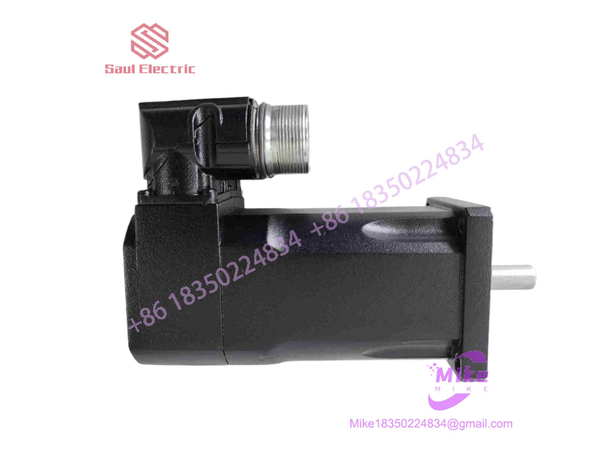
8MSA2S.R0-K4
Key Technical Specifications
| Parameter | Specification | Field Note / Operational Limit |
| Nominal Speed | 6000 RPM | Continuous operational limit under rated bus voltage (330 VAC) |
| Stall Torque (M_0) | ~0.20 Nm | Continuous static output (\Delta T = 100 K) |
| Peak Torque (M_{\max}) | ~0.80 Nm | Short-duration acceleration transient allowance |
| Rated Current (I_n) | ~0.43 A | Continuous phase current consumption at rated speed |
| Feedback Unit | Resolver (R0 Variant) | Analog excitation signal for absolute position within one revolution |
| Flange Size | Size 2 (~55mm Flange) | Compact mounting footprint for tight multi-axis toolheads |
| Winding Connection | Three-Phase Star Connection | High-density copper stator winding |
| Protection Class | IP65 | Housing sealed against industrial dust and light moisture ingress |
| Cooling Method | Natural Convection (Self-Cooling) | Requires unhindered ambient airflow around aluminum casing |
| Thermal Protection | Integrated Thermal Sensor | Monitored directly by drive feedback wiring loop |
Global Sourcing & Live-Test SOP (Transparency Core)
Sourcing small-frame surplus servo motors demands thorough testing—minor shaft misalignment or degraded resolver windings can pass simple visual checks while causing instant drive faults under load. Here is our exact multi-stage quality control workflow before any stock ships:
- Inbound Mechanical Inspection:
We clamp the shaft under digital dial indicators to verify radial runout remains within OEM spec (under 0.015mm). Serial number plates are verified against B&R build databases to catch counterfeit relabeling.
- Drive Rack Simulation:
The unit is connected to an authentic test station equipped with an ACOPOS 8V multi-axis inverter channel running B&R Automation Studio software.
- Diagnostic Test Routine:
- Resolver Phase Handshake: We capture excitation carrier waves on an oscilloscope to confirm zero signal attenuation and verify correct transformation ratio angles.
- Full-Speed Dynamic Test: Running a continuous 3-hour velocity profile up to 6000 RPM allows us to measure bearing acoustic noise and track winding temperature stabilization.
- Insulation Megger Inspection: A 1000V DC surge test across phase-to-phase and phase-to-ground guarantees zero dielectric breakdown across stator windings.
- Final ESD Packaging:
Shaft extensions receive protective grease and caps. The motor is sealed in anti-static ESD bags and cradled in custom high-density foam packaging.
The Field Engineer’s Pitfall Guide
- ❗ Resolver Null-Point Offset Errors:
Never loosen the rear end-cap assembly on an
R0motor variant. On B&R motors, the physical alignment of the resolver rotor relative to the motor’s magnetic poles is factory-pinned. Shifting the resolver body even by a hair alters the commutation angle, causing the ACOPOS drive to draw massive current spikes or throwCommutation Angle Error 9005immediately upon enabling power. - ❗ Connector Pin Strain on Small-Gauge Cables:
The miniature circular feedback and power connectors on Size 2 motors use fine-gauge contacts. Pulling or flexing cables at sharp angles directly behind the connector boot can pull signal pins back inside the insulator shell, resulting in intermittent
Resolver Signal Lossfaults that appear only when the axis head moves. - ❗ Forcing Coupling Assemblies onto Precision Shafts:
Because the shaft diameter on a Size 2 motor is small, striking a gear or pulley coupling with a hammer will collapse the internal ball bearing races and fracture the internal resolver winding bobbin — permanently destroying the motor before it ever runs. Always use a proper threaded puller tool when installing couplings.
Intent-Driven FAQ
Will my ACOPOS drive automatically configure itself when I install this 8MSA2S motor?
If your system uses standard ACOPOS motor database entries in Automation Studio, the drive matches the model code 8MSA2S.R0-K4 and automatically assigns current limits, resolver excitation frequencies, and velocity loop gains.
What is the primary difference between resolver feedback (R0) and optical encoders (E0/EB)?
Resolver feedback (R0) relies on electromagnetic inductive transformation rather than glass optical disks. Resolvers tolerate harsh mechanical shock, extreme temperature swings, and industrial vibration much better, making them far more durable in rugged industrial settings.
Can I hot-swap this motor while the ACOPOS drive backplane has power?
No. Disconnecting or plugging in motor power or feedback cables while the DC bus is energized creates electrical arcing across terminal pins and induces high-voltage noise spikes that can damage both the resolver feedback electronics and the drive’s analog input channels.
What should I check if Automation Studio throws a motor overtemperature alarm immediately after wiring?
First, check the resolver feedback cable connector. The motor’s internal thermal sensor signal routes through dedicated pins inside the feedback connector. An unseated connector or pushed-back pin creates an open circuit, which the drive interprets as an extreme thermal fault above 150^\circC.
How can I confirm if a replacement 8MSA2S motor is factory unused?
Examine the mounting flange face, keyway/shaft surface, and gold connector pins. Genuine factory-sealed stock exhibits zero bolt compression marks around the flange holes, unmarred shaft surfaces, pristine connector pins without insertion scratches, and original protective caps intact over the shaft extension.





