Description
Alstom MAE99-04 | 8-Channel Serial Interface Isolation Unit
Dynamic Product Introduction
A serial communication fault does not always originate in the controller. In older industrial installations, ground potential differences, field-side electrical noise, and deteriorated termination hardware can disrupt communication between plant equipment and the control system. Replacing the wrong component, however, can turn a localized communication problem into a much larger commissioning issue.
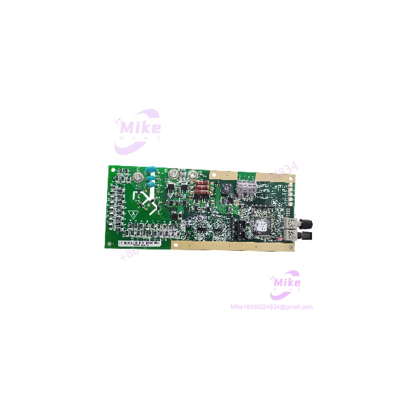
The Alstom MAE99-04 addresses the field-interface side of that problem. Designed as an 8-channel serial interface isolation unit, it connects plant wiring to a compatible PMC-Sweet16 serial interface module through dedicated cabling. The original product documentation identifies both RS-232 and RS-485 wiring arrangements, making correct interface configuration a key part of replacement planning.
For maintenance teams supporting legacy Alstom or Converteam control equipment, the MAE99-04 can be relevant when restoring an existing serial communication architecture without redesigning the entire control system. Its value is architectural compatibility—not a claimed increase in processing speed, logic execution rate, or communication bandwidth.
Honestly, when dealing with legacy interface hardware, preserving the original wiring scheme and verifying the exact termination-panel revision matter more than chasing unverified performance claims.
MAE99-04
Key Technical Specifications
The following specifications are based on available product documentation. Parameters not conclusively established by the original documentation are identified accordingly.
- Manufacturer: Alstom Controls
- Model Number: MAE99-04
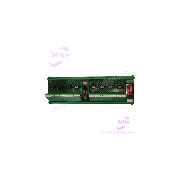
- Product Type: 8-channel serial interface isolation and termination panel
- Channel Capacity: 8 serial interface ports
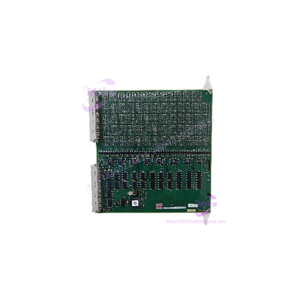
- Host Interface: SBS-Greenspring PMC-Sweet16 serial interface module
- Serial Interface Arrangement: RS-232 or RS-485 wiring configurations
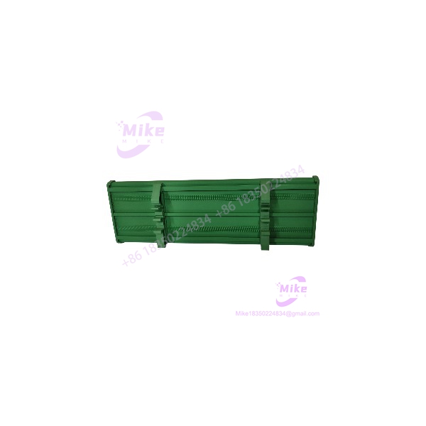
- Mechanical Construction: PCB assembly in a DIN-rail-mounted Phoenix base
- PCB Dimensions: Approximately 262 × 72 mm
- Field Connections: Spring-cage terminal blocks
- Cable Shielding: Dedicated earth-bar arrangement for plant-side cable screens
- System Connection: Dedicated cable to one of the PMC-Sweet16 8-channel connectors
- Firmware / Revision: Confirm the installed hardware revision and host-side configuration; no universal firmware compatibility range is verified.
The original MAE 99-04 product data identifies the termination panel, mechanical construction, port layout, and host-interface relationship.
Procurement note: Do not treat generic online claims about baud rate, isolation voltage, power consumption, or operating temperature as verified acceptance criteria without the applicable OEM documentation. Those values should be confirmed against the exact assembly revision before installation.
Global Sourcing & Live-Test SOP (Transparency Core)
For legacy serial interface hardware, a clean exterior is not proof of electrical integrity. The Alstom MAE99-04 should be evaluated against its actual interface function, terminal layout, and intended host configuration—not simply accepted because the part number matches.
The following is a recommended inspection and qualification procedure for surplus or replacement inventory. It is not a claim that the specific listed unit has already passed these tests.
Inbound Verification
- Confirm the MAE99-04 part number against the physical nameplate and PCB markings.
- Record the serial number, hardware revision, and visible manufacturing identifiers.
- Inspect available OEM documentation, chain-of-custody records, and supplier declarations.
- Check terminal blocks, PCB traces, isolation components, and connectors for corrosion, contamination, or previous repair work.
- Photograph the received assembly before cleaning or repackaging.
Where factory-sealed stock is offered, verify that the packaging and seals are consistent with the supplier’s description. Factory-sealed status should not be confused with proof of current operational functionality.
Live Simulation & Functional Testing
A meaningful acceptance test requires a compatible test environment.
For the , the test setup should include the correct PMC-Sweet16 interface hardware, the appropriate carrier/host arrangement, and the required cabling. An unrelated PLC rack or generic power-up test is not an adequate substitute.
Recommended checks:
- Verify power requirements against the applicable OEM documentation before energizing.
- Confirm the termination panel’s connection to the correct 8-channel serial interface connector.
- Exercise each of the eight ports using an appropriate serial test arrangement.
- Verify transmit and receive behavior against the intended RS-232 or RS-485 configuration.
- Check channel isolation using a suitable, controlled test procedure that does not exceed the assembly’s documented limits.
- Record test equipment, setup, test conditions, and observed results.
Protocol qualification: The is a serial interface termination panel, not a universal Modbus or Profibus gateway. Protocol validation must be performed through the host and field devices using the actual installed configuration. Do not assume that a generic Modbus handshake or Profibus test alone establishes compatibility.
Diagnostics & Burn-In
For units intended for critical service, the inspection record should include:
- Individual port test results
- Abnormal LED behavior, where applicable
- Connector and terminal inspection results
- Electrical measurements taken within documented limits
- Temperature observations during an extended powered test
A 24-hour heat run may be included in a buyer-specific qualification plan, but it should not be represented as a completed test unless the supplier provides supporting records.
Final Preparation & Shipment
Before dispatch, the supplier should:
- Record the verified part number and hardware revision.
- Document the condition as new surplus, used, refurbished, or repaired.
- Include available functional test results.
- Protect the assembly in ESD-safe packaging.
- Secure the terminal area against shipping damage.
- Provide traceable packaging and shipment records.
For an intended for an outage-critical application, request the inspection report before releasing the purchase order—not after the unit arrives.
The Field Engineer’s Pitfall Guide
❗ Warning 1: RS-232 and RS-485 Wiring Are Not Interchangeable by Assumption
The documentation identifies different plant-side wiring arrangements. Before removing the existing panel, photograph every terminal connection and document the active interface type. A replacement with the correct model number can still create a communication failure if the field wiring is reconstructed incorrectly.
I’ve seen troubleshooting efforts drag on because the team assumed that matching terminal positions meant matching signal assignments. Verify TX, RX, signal common, and differential-pair connections against the applicable wiring diagram.
❗ Warning 2: Do Not Ignore the Host-Side PMC-Sweet16 Connection
The is designed to interface with a specific serial interface architecture. It is not a generic serial expansion card that can be connected to any controller or backplane.
Before installation, verify the host carrier, PMC-Sweet16 module, cable assembly, and connector assignment. A physically compatible cable is not necessarily electrically compatible (particularly in legacy systems where replacement harnesses may have been assembled or modified in the field).
❗ Warning 3: Grounding and Cable Shields Can Make or Break the Installation
The product documentation identifies an earth-bar arrangement for plant-side cable screens. Do not casually omit this connection or assume that the cabinet’s protective earth automatically reproduces the original shielding scheme.
During commissioning, check the grounding arrangement against the approved drawings. Incorrect shield termination can introduce noise or ground-loop problems that appear to be a defective interface panel.
Intent-Driven FAQ
Q1: What does the Alstom actually do?
The is an 8-channel serial interface isolation and termination panel. It connects plant-side serial wiring to a compatible PMC-Sweet16 serial interface module. It is not a standalone CPU or general-purpose digital input/output card.
Q2: Can I replace my existing without changing the control system?
Potentially, provided the replacement matches the installed hardware configuration. Confirm the exact part number, terminal arrangement, interface type, cable connection, and host compatibility before installation. A matching model number alone does not establish that a unit is ready for immediate service.
Q3: Does the support Modbus RTU?
The provides serial interface isolation; it does not independently establish Modbus RTU support. Modbus compatibility depends on the host-side serial interface, application configuration, connected devices, and communication settings.
Q4: Can I hot-swap the while the control system is running?
Do not assume hot-swap capability. The available product description does not establish a universal energized replacement procedure. Confirm the approved maintenance procedure and determine whether the associated serial channels can be safely isolated before removing the panel.
Q5: Is the Alstom obsolete, and can I still source it?
The belongs to a legacy control architecture, so procurement may involve surplus or previously installed inventory. Current OEM production status and authorized replacement availability should be confirmed directly. When evaluating surplus stock, request physical identification photographs, traceability records, and documented test results.
Q6: Can I downgrade firmware or use a different revision with the ?
The is a termination panel, not a programmable controller with an independently established firmware-downgrade procedure. Host-side firmware and configuration compatibility should be checked separately. Do not apply generic firmware upgrade or downgrade procedures intended for CPUs or communication processors to this assembly.
Q7: What warranty should I expect when buying an Alstom ?
Warranty coverage depends on the supplier and the condition sold. New surplus, used, and refurbished units may carry different terms. Before ordering, obtain written confirmation of the warranty duration, coverage start date, return authorization process, and remedy for a unit that fails functional testing. Do not assume that a seller’s general warranty applies identically to every inventory condition.