Description
YOKOGAWA F3PU10-0N | FA-M3 AC Power Supply Module
Dynamic Product Introduction
A PLC rack failure does not always start with a failed CPU. In many FA-M3 systems, the power module is the first component that quietly brings an entire control rack offline. The YOKOGAWA F3PU10-0N is the dedicated AC power supply module designed to keep compact FA-M3 base configurations operating with stable 5 VDC logic power.
The F3PU10-0N accepts 100–240 VAC single-phase input at 50/60 Hz and provides a regulated 5 VDC, 2.0 A output for compatible FA-M3 base units. It is designed specifically for F3BU04 and F3BU06 base modules, meaning replacement decisions must consider the installed base configuration rather than only matching voltage ratings.
Compared with larger FA-M3 power modules such as the F3PU20-0N, the F3PU10-0N targets smaller rack assemblies where lower power demand is expected. The difference is not just physical size; the output current capacity, compatible base module range, and rack loading must align with the actual installation.
In field maintenance work, power modules are often replaced too quickly without checking downstream current demand. A replacement can show a normal RDY indication and still fail when additional I/O modules increase the 5 VDC load beyond the intended range.
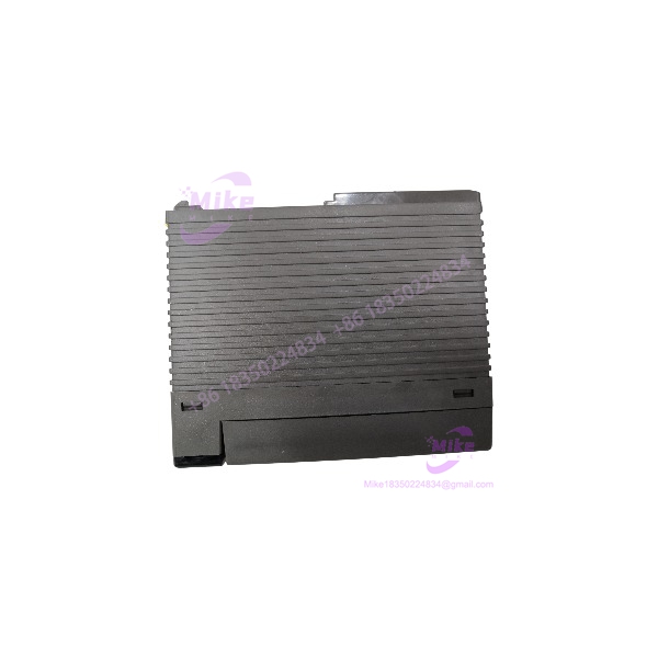
F3PU10-0N
Key Technical Specifications
- Model: F3PU10-0N
- Manufacturer: YOKOGAWA
- PLC Platform: FA-M3 Range-Free Multi-Controller
- Module Type: AC power supply module
- Input Voltage: 100–240 VAC single phase
- Input Frequency: 50/60 Hz
- Allowable Voltage Range: 85–264 VAC
- Rated Output Voltage: 5 VDC
- Rated Output Current: 2.0 A
- Power Consumption: 35 VA
- Maximum Inrush Current:
- 20 A max. at 120 VAC
- 45 A max. at 240 VAC
- Internal Protection: Built-in time-lag fuse
- Momentary Power Failure Tolerance: 20 ms standard mode
- FAIL Contact Output: Available
- FAIL Contact Rating: 24 VDC, 0.3 A
- Dimensions: Approx. 28.9 × 100 × 83.2 mm
- Weight: Approx. 190 g
- Compatible Base Modules: F3BU04, F3BU06
The F3PU10-0N and F3PU10-0S share the same electrical characteristics, but the terminal block screw specification differs. The “S” version uses a different terminal screw size and is the CE-marking compliant variant, while the “N” version is not CE-marking compliant.
Global Sourcing & Live-Test SOP
For surplus inventory, a simple resistance check or visual inspection is not enough.
Power modules are deceptively simple. A damaged regulator stage, aging capacitor, unstable output under load, or degraded protection circuit can cause intermittent PLC faults that are difficult to trace.
Inbound Verification
Every incoming should be checked for:
- Exact model marking
- Serial number
- Manufacturing information
- Terminal condition
- Housing damage
- Burn marks or overheating evidence
- Connector condition
- Previous storage environment
Confirm the module is actually an and not an F3PU20-0N or F3PU10-0S substitute.
The main differences:
- 5 VDC / 2.0 A output
- F3PU20-0N: 5 VDC / 4.3 A output
- Different compatible base module ranges
Using a physically similar module with the wrong rack compatibility can create installation problems.
Live Simulation
A proper power validation requires a controlled FA-M3 test rack.
Recommended procedure:
- Install the into a compatible F3BU04 or F3BU06 base.
- Apply 100–240 VAC input.
- Verify RDY indicator operation.
- Measure 5 VDC output voltage.
- Apply representative load conditions.
- Monitor voltage stability during startup and shutdown.
The goal is not only confirming that 5 VDC exists. The goal is confirming that the supply remains stable when the CPU and I/O modules draw current.
Diagnostics
Recommended checks:
- Measure AC input voltage.
- Verify 5 VDC output with a calibrated multimeter.
- Test startup behavior after power interruption.
- Confirm FAIL contact operation.
- Check voltage ripple under load.
- Perform repeated power cycles.
- Run extended temperature operation.
The FAIL signal contacts should also be tested because they provide external indication when the power supply detects abnormal conditions. The contact output changes state during system failure or power failure conditions.
A Fluke multimeter and controlled electronic load provide a more reliable evaluation than an unloaded voltage measurement.
Final Preparation
Before shipment:
- Record measured output voltage.
- Record test load current.
- Record physical condition.
- Protect AC terminals.
- Use ESD-safe packaging.
- Include traceability information.
For industrial replacement stock, the buyer should receive not only the module but also confidence that the unit survived a controlled electrical test.
The Field Engineer’s Pitfall Guide
❗ Do not replace the based only on 5 VDC output.
A 5 VDC power supply is not automatically compatible. The is designed for F3BU04 and F3BU06 base modules, while larger FA-M3 bases require different power modules. I have seen maintenance teams install a higher-capacity supply into the wrong rack and spend hours chasing compatibility issues.
❗ Do not ignore rack current calculations.
The provides 2.0 A at 5 VDC. Adding extra CPU, communication, or I/O modules without checking total 5 VDC consumption can overload the supply. The failure often appears as random resets rather than an obvious power-supply alarm.
❗ Do not confuse with F3PU10-0S.
The two models are electrically similar, but terminal hardware differs. The CE compliance status also differs. For projects requiring compliance documentation, selecting the correct suffix matters.
Intent-Driven FAQ
What does the YOKOGAWA do?
The is an FA-M3 power supply module that converts 100–240 VAC input into regulated 5 VDC power for compatible Yokogawa PLC base modules.
Is the compatible with F3BU09 or F3BU13 bases?
No. The is intended for F3BU04 and F3BU06 base modules. Larger FA-M3 bases such as F3BU09 and F3BU13 use different power supply modules, including the F3PU20 series.
Can I replace an with an F3PU10-0S?
Electrically, they are equivalent in output specifications, but terminal screw configuration and compliance details differ. Confirm the project requirements before substitution.
What output voltage should I measure on the ?
The expected rated output is 5 VDC. The measurement should be performed under load because an unloaded supply can appear healthy while failing during actual PLC operation.
Does the support hot swapping?
No. Treat it as an AC-powered PLC rack component. Power should be isolated before removal or wiring work.
How can I test a used before installation?
Check:
- AC input acceptance
- 5 VDC output stability
- FAIL contact behavior
- Startup recovery
- Load performance
- Physical condition
A proper load test is more meaningful than simply confirming the RDY LED.
Is the still useful for legacy FA-M3 systems?
Yes. Many installed FA-M3 systems continue operating in industrial environments where maintaining original rack architecture is preferred over complete migration. The key procurement requirement is matching the exact base module and power requirements.
Procurement verdict: The is a dedicated FA-M3 power supply module designed for compact PLC rack configurations. Its value is not in advanced functionality; it is in delivering the correct 5 VDC power source for a specific Yokogawa architecture.
For replacement sourcing, verify the complete combination: model, compatible F3BU base module, 5 VDC current demand, terminal requirements, and tested electrical condition. A correct match prevents unnecessary PLC troubleshooting caused by a mismatched power subsystem.