Description
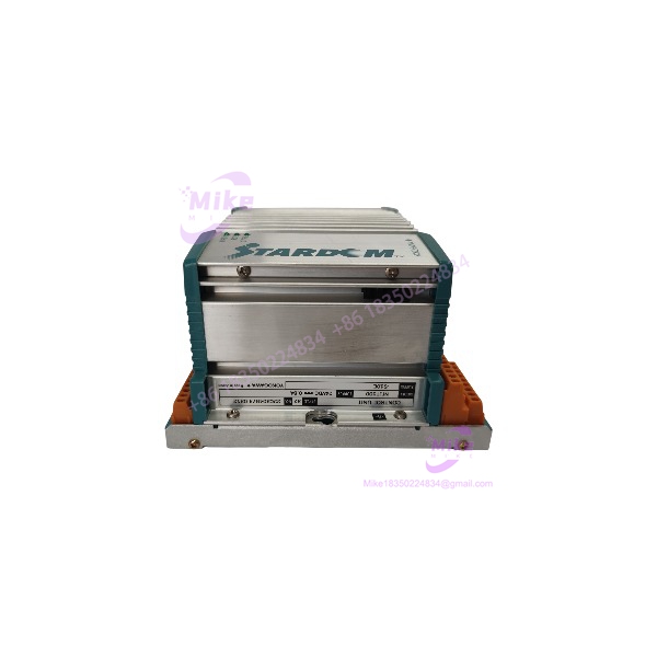
Yokogawa EB401-10 | 10 Mbps ER Bus Interface Module
Product Introduction
The Yokogawa EB401-10 is not a general-purpose Ethernet communication card. It is a dedicated ER Bus Interface Master Module used within Yokogawa’s field-control architecture to connect remote ER Bus nodes to the control system.
That distinction is important when evaluating replacement inventory. The EB401 sits between Yokogawa’s control-system infrastructure and an ER Bus network; it is therefore tied to the FCU/node architecture, slot position, bus topology, termination, and applicable Yokogawa configuration. Yokogawa’s system documentation explicitly describes ER Bus Node Units as remote nodes connected through an EB401 installed in the relevant control-system node.
For an existing plant, this is primarily a communications-infrastructure spare, not an I/O module. If an EB401 fails, the problem can extend beyond one field signal—the affected ER Bus segment or remote node group may become inaccessible.
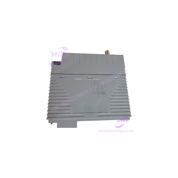
EB401-10
Key Technical Specifications
Communication
- Function: ER Bus interface/master function
- Bus: Yokogawa ER Bus
- Physical layer: IEEE 802.3 10BASE-2
- Communication rate: 10 Mbps
- Connector: BNC
- Transmission medium: Coaxial cable
- Maximum specified segment distance: Approximately 185 m with the applicable Yokogawa cable configuration
- Network architecture: ER Bus connection between local control infrastructure and remote ER Bus nodes
The 10BASE-2 specification is significant because this is legacy coaxial Ethernet technology, not modern RJ45 copper Ethernet or ordinary plant Ethernet. Yokogawa’s own documentation describes the EB401 as the interface required when connecting an ER Bus Node Unit to an FCU.
Electrical / Mechanical
- Current consumption: Approximately 0.7 A
- Width: Approximately 32.8 mm
- Height: Approximately 144.65 mm
- Depth: Approximately 125.5 mm
- Weight: Approximately 0.3 kg
- Mounting: Dedicated Yokogawa control-system module slot
System Installation
Yokogawa documentation specifies that an EB401 must be installed in an odd-numbered slot for a single configuration, with the adjacent position to the right kept empty in that configuration. The same system documentation also describes the as the interface used to connect ER Bus Node Units to an FCU.
This is an important commissioning detail. The module should not be treated like a freely positionable PLC communication card.
System Architecture
A simplified architecture is:
CENTUM / FCU → → ER Bus → ER Bus Node Unit → I/O Modules
Yokogawa describes the ER Bus Node Unit as a remote node that communicates with the FCU through the ER Bus. The provides the interface between the FCU-side control architecture and that remote bus.
This architecture explains why the -10 is commonly encountered alongside Yokogawa field-control hardware rather than as a standalone Ethernet component.
Yokogawa documentation also states that the is installed on the FCU when an ER Bus Node Unit is connected.
Application Scenarios & Engineering Pain Points
1. Remote FIO / ER Bus Node Communication
The primary application is connecting remote ER Bus Node Units to Yokogawa’s field-control infrastructure.
The handles the dedicated ER Bus communication path; it does not replace an analog-input, digital-output, or other field I/O module.
2. CENTUM System Expansion
Older Yokogawa installations can use remote node architecture to distribute I/O rather than bringing every field termination physically back to a central cabinet.
The is part of that distributed architecture.
3. Redundant Communication Architecture
Where the installed system supports redundant arrangements, two interface modules can be used to increase communication availability. This is particularly relevant to process-control systems where loss of an entire remote I/O communication path is unacceptable.
4. Legacy Plant Maintenance
This is arguably the most important procurement use case.
A failed can be difficult to replace through normal new-equipment channels because it belongs to a mature Yokogawa architecture. Used and refurbished inventory therefore appears frequently in maintenance sourcing.
For a critical spare, however, “powers up” is not an adequate acceptance criterion.
QA & Live Testing SOP
1. Model and Style Verification
Confirm the physical label shows:
- Correct suffix/configuration
- Hardware/style information
- Manufacturer markings
- Revision information where present
Do not purchase solely from an abbreviated listing title such as ” PLC Module.”
2. Physical Inspection
Inspect:
- BNC connector
- Module edge connector
- PCB condition
- Housing
- Front indicators
- Corrosion
- Contamination
- Signs of overheating or previous repair
The BNC interface deserves particular attention because damage to the connector can cause intermittent ER Bus faults that are difficult to diagnose.
3. Power-Up Test
Install the module in an appropriate test environment and verify:
- Module initialization
- Normal status indication
- No persistent module fault
- Correct recognition by the control-system hardware
4. ER Bus Communication Test
A proper test should establish communication with a compatible ER Bus node.
Verify:
- Bus link establishment
- Node recognition
- Stable communication
- No recurring communication errors
- Correct redundant-path behavior where applicable
5. Long-Duration Stability Test
For a safety-critical or production spare, I would run the module under communication load rather than stopping after a successful startup.
Monitor for:
- Intermittent bus loss
- CRC/error events
- Module resets
- Communication retries
- Excessive temperature
- Status-indicator changes
6. Documentation
Record:
- Exact model
- Hardware/style information
- Test configuration
- ER Bus node used for testing
- Communication results
- Fault/event history
- Photographs
- Final acceptance status
Field Engineer’s Pitfall Guide
❗ 1. Do not treat -10 as a conventional Ethernet card.
The module uses Yokogawa’s dedicated ER Bus architecture and a 10BASE-2 physical interface. A modern Ethernet switch or RJ45 Ethernet module is not a functional substitute.
❗ 2. Verify the slot position before installation.
Yokogawa’s system documentation specifies an odd-numbered slot for a single configuration and requires the adjacent right-hand slot to remain empty in that arrangement.
❗ 3. Do not test only the module in isolation.
An can pass a basic power-up test while the actual ER Bus communication path remains defective. The acceptance test should include a compatible ER Bus node and sustained communication.
Intent-Driven FAQ
What is the Yokogawa -10?
The Yokogawa EB401-10 is an ER Bus Interface Master Module used to connect Yokogawa control-system infrastructure with remote ER Bus Node Units.
Is an I/O module?
No. It is a communication/interface module. The actual field I/O is installed in the associated node architecture.
What communication protoces use?
It uses Yokogawa’s ER Bus architecture with an IEEE 802.3 10BASE-2 physical interface. Yokogawa documentation specifically identifies as the interface for connecting ER Bus Node Units to the FCU.
es use an RJ45 connector?
No. The documented physical interface uses a BNC connector associated with the 10BASE-2 ER Bus connection.
What is the communication speed?
he is specified for 10 Mbps ER Bus communication.