Description
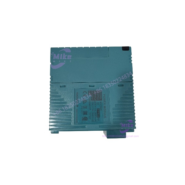
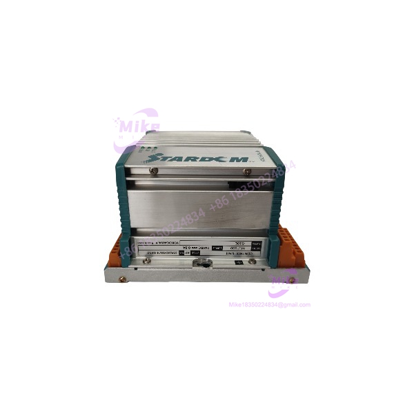
NFJT100-S10E | Yokogawa Fieldbus Terminal Board Unit
Dynamic Product Introduction
Tracking down signal degradation in process automation cabinets usually leads right to worn or corroded termination assemblies. When analog loops drift or fieldbus handshakes throw physical layer faults, a failing terminal board like the NFJT100-S10E is frequently the root cause. Swapping the base board directly restores terminal contact integrity without requiring expensive module redesigns or re-running cabinet field cables.
The NFJT100-S10E provides passive signal route consolidation between field instruments and Yokogawa STARDOM controller I/O racks. Built with high-grade shielding and secure terminal screw mounts, it isolates control electronics from field transients while keeping field wiring organized and easy to trace.
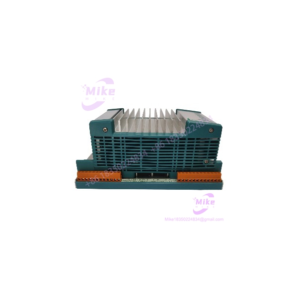
NFJT100-S10E
Key Technical Specifications
- Model Number: NFJT100-S10E
- Manufacturer: Yokogawa
- Module Classification: Signal Terminal / Connection Board
- System Compatibility: STARDOM FCN Series Nodes
- Terminal Type: Screw Terminal Block Assembly
- Connector Style: Multi-pin ribbon / cable connector interface
- Insulation Resistance: 100 MΩ minimum at 500 V DC
- Operating Temperature: -10°C to +55°C (14°F to 131°F)
- Storage Temperature: -20°C to +70°C (-4°F to 158°F)
- Mounting Method: DIN-rail or dedicated baseplate installation
Global Sourcing & Live-Test SOP (Transparency Core)
To guarantee operational stability when installing replacement termination units, every item goes through a rigorous quality control check prior to shipment.
1.Inbound Physical & Terminal Inspection:Prerequisite。
Verify serial tags and part codes against OEM records. Inspect terminal screws, track traces, and connector pins for oxidation, corrosion, or mechanical wear.
2.Continuity & Insulation Test:5 min。
Measure trace resistance and pin-to-pin isolation across all terminal paths using a digital multimeter to confirm zero internal short circuits or open traces.
3.Live Signal Simulation:20 min。
Attach the NFJT100-S10E to a STARDOM I/O test rig. Pass analog current signals (4-20 mA) and digital pulses through the terminal channels to confirm signal continuity under load.
4.Thermal Burn-In & ESD Sealing:24 Hours。
Subject the board to a 24-hour thermal soak under power inside a test chamber. Once cleared, pack the unit in an ESD-safe shield bag with a fresh desiccant packet.
The Field Engineer’s Pitfall Guide
Critical Installation Warnings
Verify terminal cable pinouts, shield ground connections, and screw torques prior to energizing active process loops.
❗ 1. Over-Torquing Field Terminal Screws
—In field maintenance, technicians often apply excessive force when securing field wires to the terminal block. Over-torquing can strip internal threads or fracture the underlying trace solder joints on the PCB, causing intermittent open circuits under cabinet vibration.
❗ 2. Improper Shield Grounding Connections
I’ve seen plant technicians troubleshoot ghost signal noise for days because signal cable shields were connected at both the NFJT100-S10E board and the field transmitter. Ground loops created by dual-point shield connections inject high-frequency noise into sensitive analog input paths. Always maintain single-point shield grounding.
❗ 3. Cable Connector Keying Misalignment
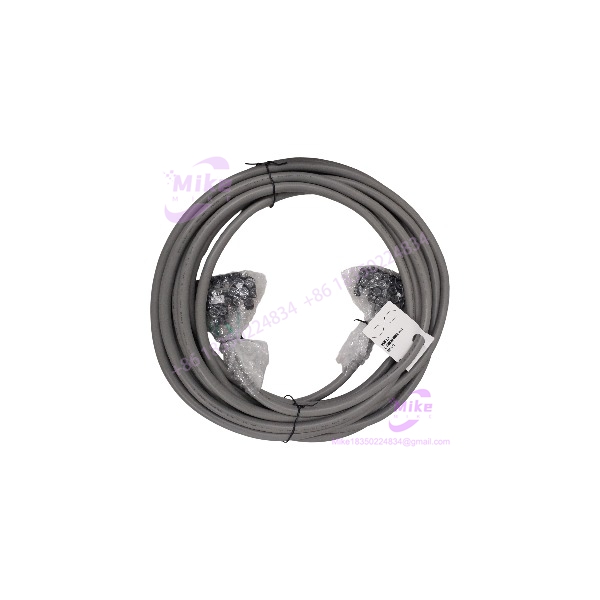
When plugging multi-pin system cables into the board header, forcing misaligned connectors can bend gold pins inside the socket. Always verify pin alignment and latch orientation before snapping the locking tabs into place.
Intent-Driven FAQ
Does replacing this terminal board require shutting down the PLC CPU?
No, as long as the specific I/O channels routed through this board can be safely isolated or bypassed in your control logic. However, field power feeding through the terminal block should be disconnected prior to swapping wiring.
Are screw terminal blocks removable on the NFJT100-S10E?
Depending on the specific sub-version, many Yokogawa terminal board assemblies feature removable terminal headers, allowing you to swap the main board without unscrewing individual field wires.
Can I use this board for both analog and digital I/O signals?
The terminal board is designed to route compatible signal types according to Yokogawa’s system cabling standards. Check your specific I/O module manual to ensure pinout compatibility.
What should I check if a channel shows an open-circuit fault after replacement?
Verify that all cable headers are fully seated in the board sockets and check for loose terminal screws on the field wire terminations.
What warranty is provided on replacement terminal boards?
Standard surplus and replacement hardware includes a full 12-month functional warranty from the date of shipment, covering material defects and board connectivity issues.