


Description
Woodward 8440-1936 | easYgen-3500 Operator Interface Panel
Architect’s Product Breakdown
The Woodward 8444-1063 operates as a high-precision multifunction relay and measuring transducer engineered within the MFR 300 product line. Designed for power generation, switchgear monitoring, and industrial electrical distribution, it continuously tracks single- and three-phase power parameters. Utilizing an advanced digital processor, the unit computes true RMS values for voltage and current regardless of harmonic distortion, transients, or line noise. It provides comprehensive protection functions—such as over/under-voltage, over/under-frequency, vector shift, and ROCOF (df/dt)—making it an industry standard for grid decoupling and generator safety.
Configuration and parameter mapping are handled via Woodward’s standard software toolkit interfaces or network connections, allowing engineers to configure trip setpoints and time delays without physical component swaps. Telemetry data and calculated power values (real, reactive, apparent power, and power factor) are transmitted smoothly to supervisory control systems via integrated CANopen or Modbus protocols.
Deploying an authentic 8444-1063 unit ensures rigorous compliance with grid interconnection codes and safeguards critical assets against power anomalies.
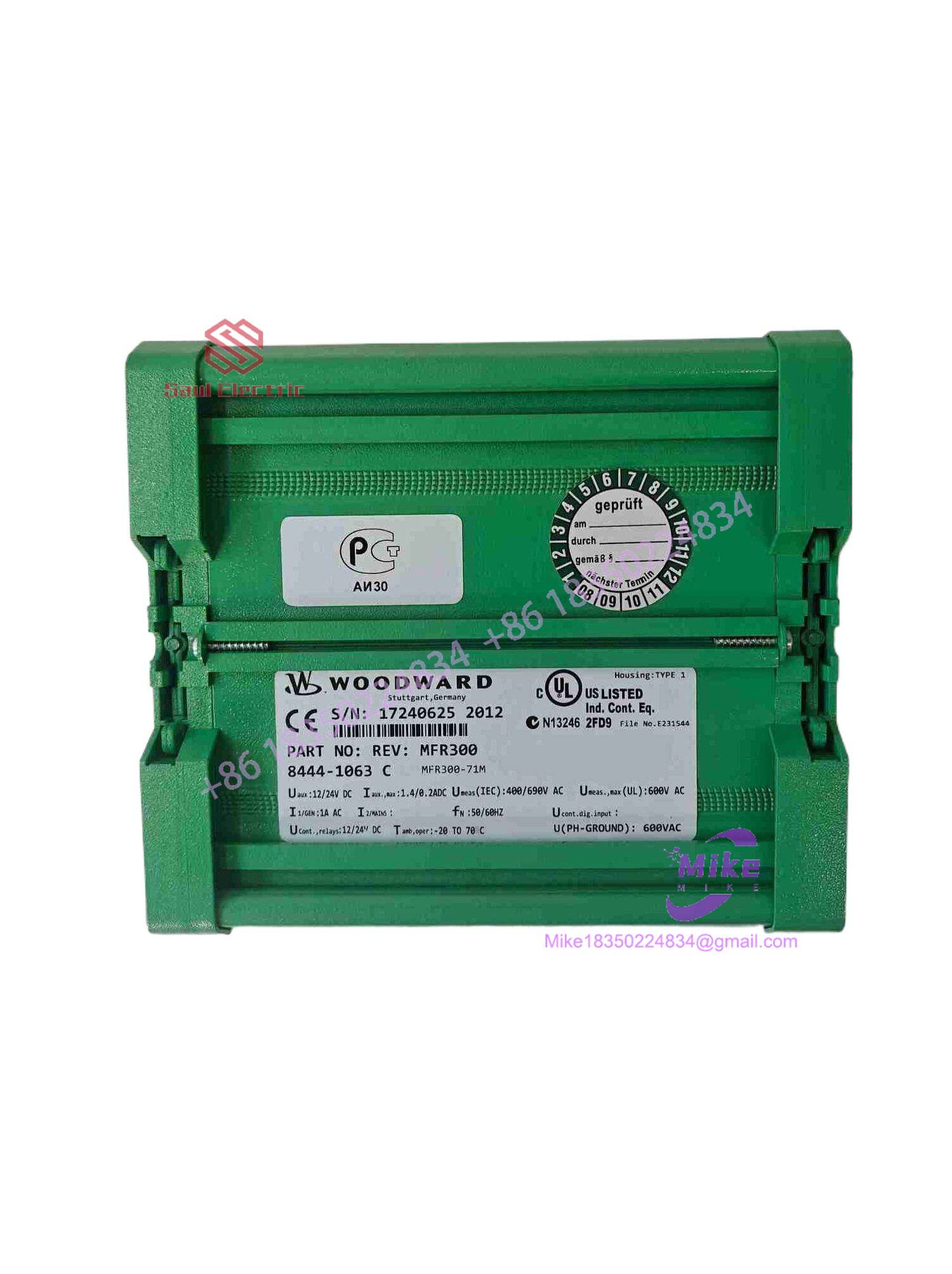
8444-1063
Key Technical Specifications
| Parameter | Technical Specification |
| Auxiliary Power Supply | 24 VDC nominal (8 to 32 VDC operating range) |
| Voltage Inputs | 3 True RMS voltage inputs (Wye / Delta configurations) |
| Current Inputs | 3 True RMS current inputs (Isolated secondary inputs) |
| Measurement Accuracy | Class 0.5 for voltage, frequency, and current; Class 1 for power/energy |
| Communication Protocols | CANopen and Modbus RTU interface |
| Relay Outputs | 4 configurable change-over trip relays + 1 “Ready for Operation” relay |
| Operating Temperature | -20°C to +70°C (-4°F to +158°F) |
| Physical Dimensions | DIN-rail / extrusion profile housing (Compact form factor) |
| Physical Weight | ~0.3 kg to 1.3 kg depending on mounting hardware configuration |
Field Engineer’s Pitfall Guide
- WARNING: Current Transformer (CT) Open-Circuit Hazard. Never disconnect secondary CT wiring from the 8444-1063 terminal block while the primary power path is energized. Opening a live CT circuit generates dangerous high-voltage spikes and ruins internal input channels. Short-circuit CT lines before servicing.
- WARNING: Incorrect Communication Baud Rate/Node ID. Replacing a unit on an active CANopen or Modbus loop without matching the node address or transmission speed will result in continuous polling timeouts on the SCADA master. Verify network parameters prior to commissioning.
- WARNING: Unfiltered Auxiliary Power Dips. Allowing the 24 VDC control power rail to sag below operating limits during heavy plant load switching can cause unintended processor resets and drop active protection relays.
QA & Testing SOP (Transparency)
- Visual & Origin Verification: Inspection of factory identification plates, part number markings (8440/8444 series rules), terminal block integrity, and housing latch conditions.
- Bench Power & Handshake: Units are mounted on an isolated test bench, powered via a regulated 24 VDC source, and verified for clean internal microprocessor boot behavior and communication port responsiveness.
- Signal Injection & Protection Test: Multi-phase AC voltage and current simulators inject precise waveforms to validate true RMS conversion accuracy, analog/logic calculation thresholds, and alarm relay actuation times.
- Final Packaging: Non-volatile memory states are cleared, and the device is sealed in an anti-static moisture barrier bag before being boxed in high-density industrial foam.
Technical FAQ
Can I hot-swap this measuring transducer while the switchgear is live?
No. Disconnecting or replacing the unit while primary PT and CT circuits are active risks dangerous open-circuit conditions and loss of system protection. Perform swaps during scheduled outages with isolated circuits.
What software is required to configure a replacement unit?
Yes, specialized software is required. You must use Woodward’s standard Software Toolkit package via the service communication port (USB/RS-232) or network bus to upload saved configuration files.
Are configuration parameters saved during a total power loss?
Yes. All site-specific settings, protection thresholds, and calibration profiles are stored in non-volatile internal flash memory, ensuring data persists safely through complete power interruptions.
What causes a continuous trip lock or grid decoupling error?
This typically occurs when line voltage, frequency, or rate-of-change metrics drift outside of the tight utility compliance windows programmed into the decoupling setpoints, or if VT/CT phase rotation is miswired.





