


Description
Woodward 8444-1019F | UMT 1 Universal Measuring Transducer
Architect’s Product Breakdown
The Woodward 8444-1019F functions as an advanced true RMS measuring transducer engineered within the UMT 1 product family. Designed for power generation, marine switchgear, and heavy industrial applications, it continuously monitors three-phase electrical networks by processing true RMS voltage and current inputs. It computes primary electrical metrics and maps them directly to high-level control loops via configurable analog outputs or digital communication ports.
Configuration and parameter adjustments are handled locally via front-panel access or remote software tools, allowing engineers to scale input transformers and fine-tune transmission ranges without physical hardware swaps. Proper shielding and ground isolation on the voltage (PT) and current (CT) input terminals are essential to prevent electromagnetic interference from distorting measurement accuracy in high-noise switchgear rooms.
Deploying a genuine 8444-1019F ensures reliable long-term performance and drop-in compatibility for legacy UMT 1 panel configurations, protecting critical power distribution systems from monitoring drift or unexpected feedback failures.
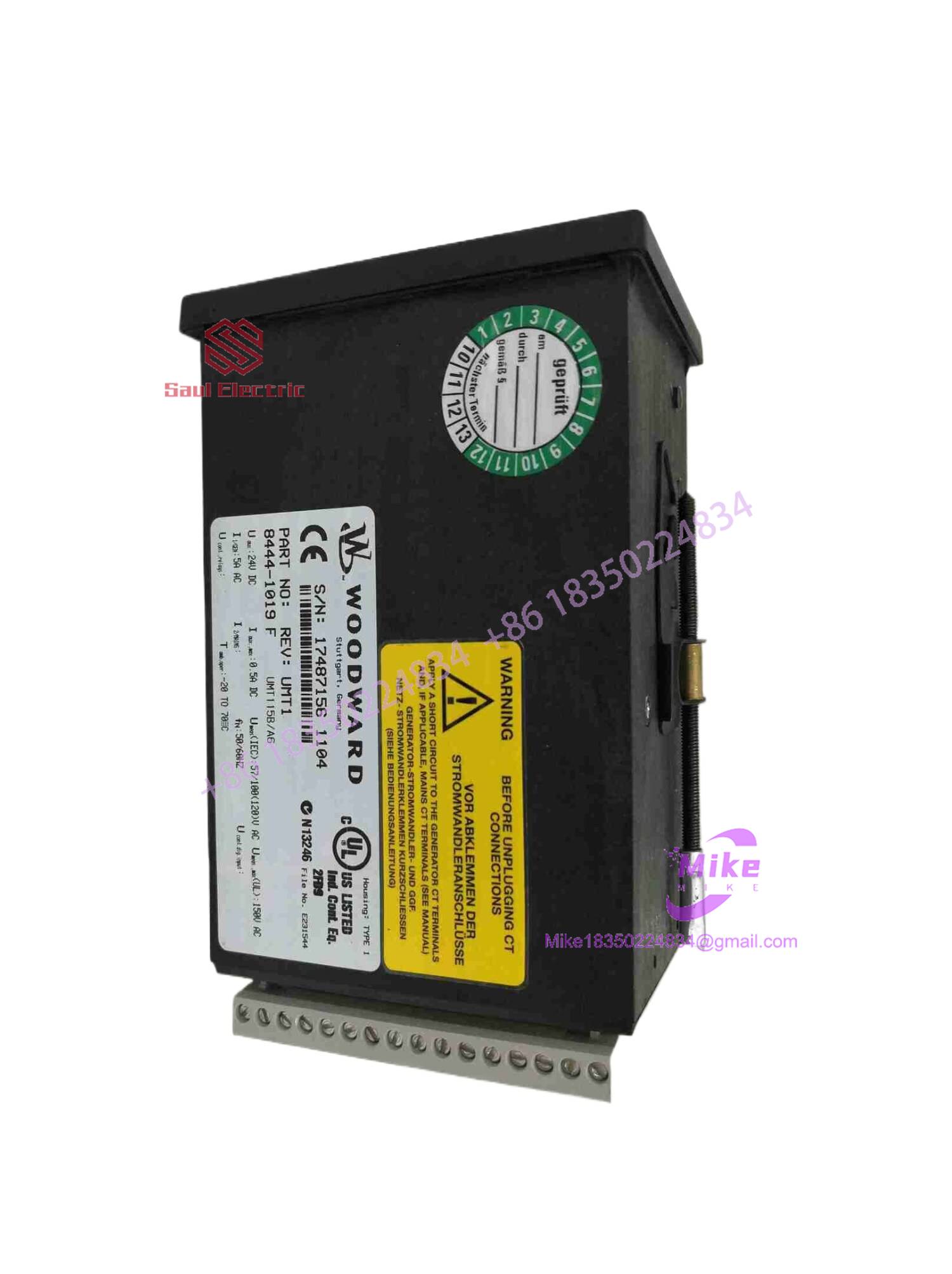
8444-1019F
4. Key Technical Specifications
| Parameter | Technical Specification |
| Auxiliary Operating Voltage (U_{aux}) | 24 VDC nominal |
| AC Voltage Sensing Inputs (U_{meas}) | 57/100 VAC up to 150 VAC max (IEC/UL ratings) |
| AC Current Sensing Inputs (I_{meas}) | Standard 5A AC secondary inputs |
| System Frequency (f_n) | 50 / 60 Hz |
| Measurement Type | True RMS three-phase voltage and current sensing |
| Communication / Outputs | Configurable analog outputs and digital communication interfaces |
| Operating Temperature | -20°C to +70°C (-4°F to +158°F) |
| Enclosure Rating | Panel/Rail mount type housing with protected rear terminals |
| Physical Weight | ~0.485 kg (1.07 lbs) |
Field Engineer’s Pitfall Guide
- WARNING: CT Secondary Open-Circuit Hazard. Never disconnect current transformer (CT) wiring from the 8444-1019F terminal block while the primary power grid is energized. Opening a live CT secondary generates lethal high-voltage spikes and destroys internal input stages. Short-circuit CT lines before performing maintenance.
- WARNING: Auxiliary Voltage Polarity. Reversing the 24 VDC auxiliary power supply connections can trip internal protection elements or fail to boot the processor. Verify DC supply polarity prior to energizing the unit.
- WARNING: Input Scaling Mismatch. Entering incorrect potential or current transformer multiplier ratios in the configuration menu will result in severely skewed analog output signals to the main PLC or SCADA system.
QA & Testing SOP (Transparency)
- Visual & Origin Verification: Detailed physical inspection of OEM manufacturing labels, housing integrity, revision markings (Rev F/UMT1), and rear pin-block terminal cleanliness.
- Bench Power & Processor Boot: Modules are placed on an isolated test rig, powered via a stable 24 VDC source, and verified for correct internal microprocessor initialization and display readiness.
- AC Signal Injection: Technicians apply calibrated multi-phase AC voltage and current sweeps to test true RMS calculation accuracy, linearity across analog output channels, and communication port handshakes.
- Final Packaging: Non-volatile test parameters are cleared where applicable, and the unit is sealed in an anti-static moisture barrier bag before being packed in high-density shock-absorbing foam.
Technical FAQ
Can I hot-swap this measuring transducer while the switchgear is live?
No. Disconnecting or replacing the unit while primary PT and CT circuits are active risks dangerous open-circuit conditions and loss of system telemetry. Perform replacements during scheduled outages with isolated circuits.
What software or tool is required to configure the UMT 1 module?
Depending on the specific parameter profile, configurations can be handled locally via the integrated display interface or through Woodward’s designated service software and communication cable linked to the serial port.
Are configuration settings preserved during a total power loss?
Yes. All calibration profiles, scaling multipliers, and configuration maps are stored in non-volatile internal memory, ensuring settings persist safely through complete auxiliary power interruptions.
What causes an inaccurate reading on the analog output channels?
Inaccurate readings are typically caused by uncalibrated PT/CT ratio settings in the software menu, loose signal wiring inducing loop resistance errors, or harmonic distortion on unconditioned primary AC lines.





