


Description
Woodward 8440-1713 | SPM-D10 Digital Synchronizer Unit
Architect’s Product Breakdown
The Woodward 8440-1713 operates as a compact, highly reliable digital synchronizer engineered for switchgear and power generation panels. Designated within the SPM-D10 product family, this controller handles the exact mathematical task of matching generator voltage, frequency, and phase angle to a live bus before issuing a deterministic breaker close command. By preventing out-of-phase synchronization, it protects expensive drive trains and alternators from severe mechanical shock.
Configuration and setup are managed through front-panel interface keys or via direct software toolkits, enabling plant engineers to adjust slip frequency limits, voltage matching windows, and breaker closure dwell times. Potential transformer (PT) inputs must be accurately scaled and isolated to ensure precise real-time phase tracking.
Integrating an 8440-1713 into legacy switchgear arrays provides a drop-in upgrade path, restoring tight synchronization control without requiring a complete overhaul of existing breaker control wiring.
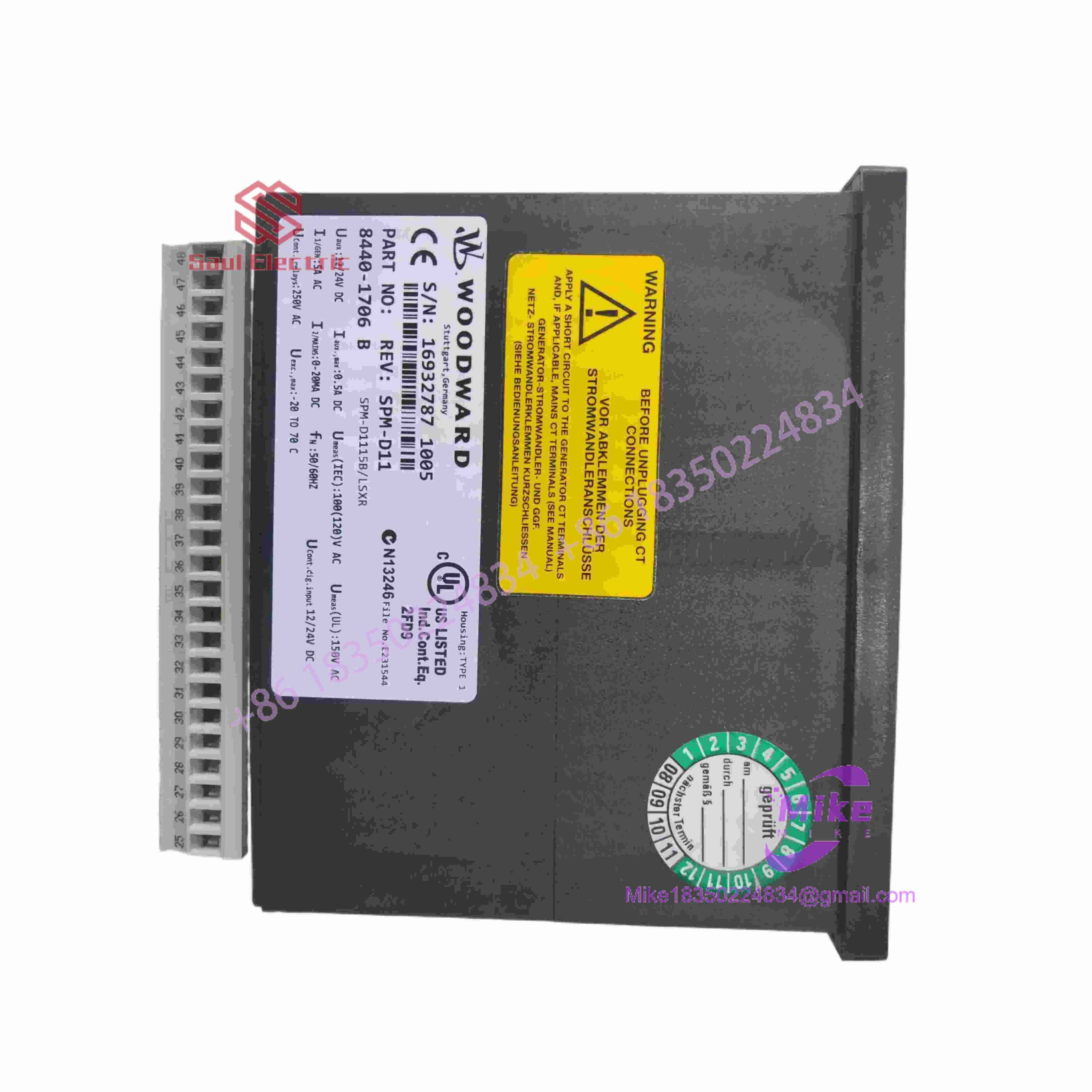
8440-1713
Key Technical Specifications
| Parameter | Technical Specification |
| Operating Voltage | 12 or 24 VDC nominal battery supply (9 to 32 VDC range) |
| Power Consumption | < 10 W typical operation |
| Voltage Sensing (PT) | Direct AC inputs matching standard switchgear PT secondary ratings |
| Outputs | Form-C relay outputs for speed/voltage bias and breaker close command |
| Control Functions | Automatic / Manual Synchro-check, Phase Matching, Dead-Bus Closing |
| Communication Ports | Serial interface for configuration and monitoring |
| Operating Temperature | -20°C to +70°C (-4°F to +158°F) |
| Enclosure Rating | Panel-mount chassis, IP20 back terminals, IP54 front face |
| Physical Weight | ~0.8 kg (1.76 lbs) |
Field Engineer’s Pitfall Guide
- WARNING: Phase Rotation Reversal. If the incoming generator phase rotation differs from the live bus PT wiring, the synchronizer will indefinitely lock out breaker closure. Verify primary and secondary phase rotation metrics before enabling auto-sync.
- WARNING: Incorrect PT Ratio Multipliers. Entering mismatched transformer voltage ratios in the configuration menu causes severe tracking calculation errors, preventing the unit from ever satisfying its sync-check permissive window.
- WARNING: Unfiltered Power Sags. A sudden drop in auxiliary DC control power below operating thresholds during heavy engine cranking can cause the module to reset mid-sequence, aborting synchronization cycles.
QA & Testing SOP (Transparency)
- Visual & Origin Verification: Detailed physical inspection of OEM manufacturing labels, terminal block pin condition, and front display/keypad integrity.
- Bench Power & Communication Handshake: Units are mounted on an isolated test bench, powered via a stable DC source, and verified for correct internal processor boot behavior.
- AC Signal Simulation: Technicians inject variable AC voltage and frequency signals into the PT inputs to test synchronization permissive windows, phase-matching accuracy, and bias relay switching.
- Final Packaging: Non-volatile test states are cleared, and the module is sealed in anti-static moisture barrier packaging enclosed by high-density shock-absorbing foam.
Technical FAQ
Can I hot-swap this synchronizer module while the generator is running?
No. Extracting or replacing the 8440-1713 while the system is online cuts off critical synchronization and speed-bias lines, risking abrupt process instability or breaker interlocks. Perform maintenance during planned outages.
What software or tool is required to configure a replacement unit?
Yes, specialized software or direct keypad configuration is required. Depending on the specific parameter profile, settings can be adjusted via the front tactile buttons or uploaded using Woodward’s matching tool suite via the communication port.
Are configuration parameters saved during a total power loss?
Yes. All site-specific settings, calibration profiles, and permissive thresholds are saved in internal non-volatile flash memory, ensuring parameters persist safely through complete power interruptions.
What causes the unit to perpetually block the synchronizing relay?
A permanent block usually indicates that the generator voltage, slip frequency, or phase angle difference is drifting outside of the tight permissive windows configured in the unit, or that PT sensing lines are uncalibrated or out of phase.





