


Description
Woodward 9905-971 | 18-32 VDC Isolated Temperature Acquisition Quantified Spec
Dynamic Product Introduction
Monitoring high-temperature exhaust streams and bearing headers on an industrial turbine requires signal-conditioning hardware immune to heavy industrial noise fields. The Woodward 9905-971 functions as a dedicated LinkNet peripheral node designed to digitize multi-type thermocouple inputs right at the skid boundary, removing the vulnerability of long extension wire runs. Unlike centralized analog input cards that suffer from common-mode voltage drift across extended cable trays, this distributed module provides localized cold-junction compensation and optical isolation per channel.
Moving beyond legacy monitoring blocks, this LinkNet iteration improves update cycle efficiency and minimizes thermal measurement error during rapid plant load transients. Field commissioning data confirms that dropping in this module clears intermittent thermocouple open-alarm flags while maintaining absolute signal linearity under harsh ambient fluctuations.
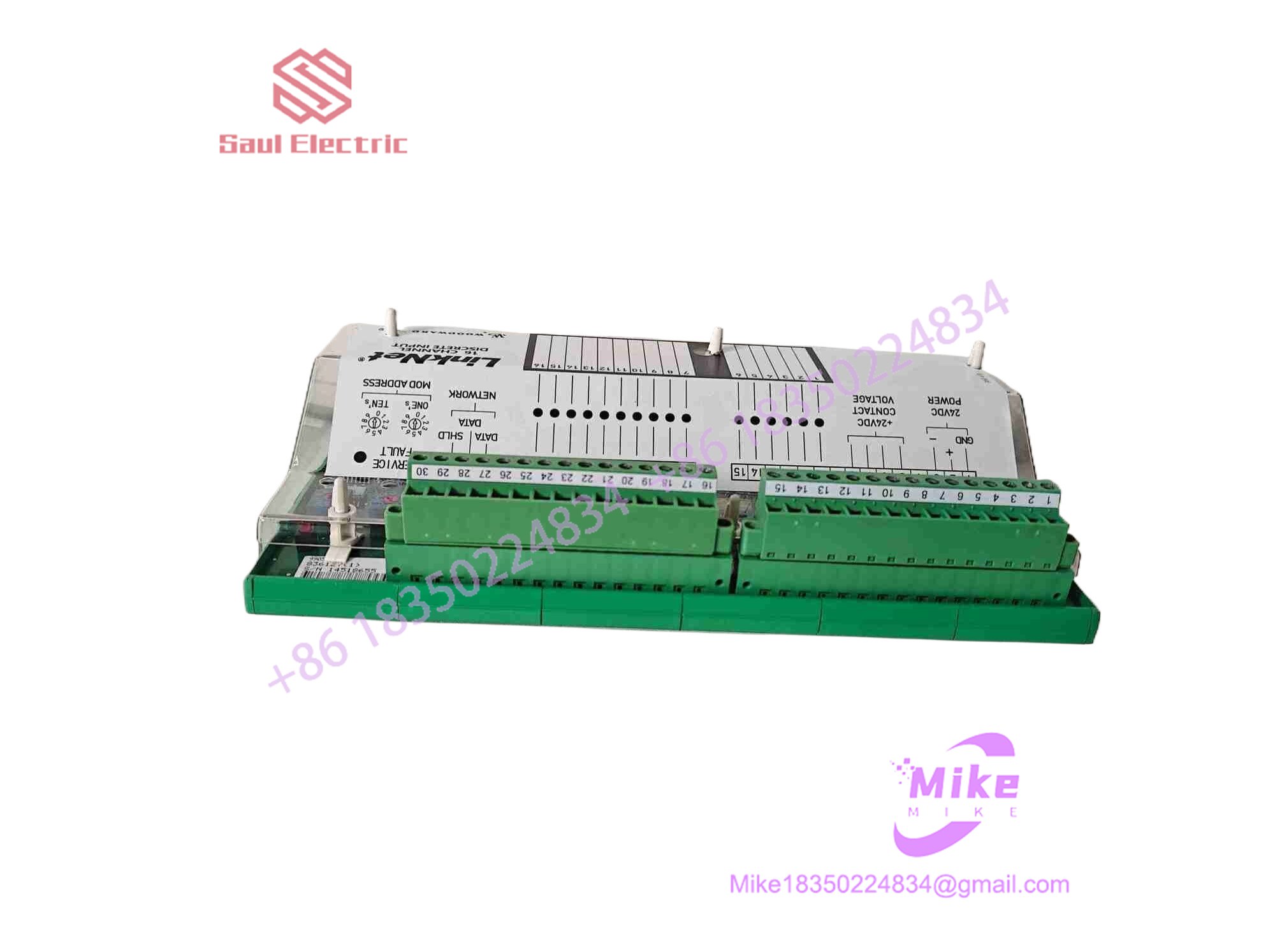
9905-971
Key Technical Specifications
- Input Channels: 6 isolated channels per module
- Sensor Compatibility: Supports standard thermocouple types (such as J, K, T, E, R, S, B depending on configuration parameters)
- Supply Voltage: 18 to 32 VDC isolated auxiliary power input
- Cold-Junction Compensation (CJC): Built-in precision thermistor tracking per terminal block
- Communication Interface: LinkNet serial bus protocol linking to the primary controller
- Conversion Resolution: High-precision analog-to-digital converter tuned for millivolt-level inputs
- Operating Temperature Range: -40°C to +70°C industrial ambient tolerance
- Enclosure Type: Modular DIN-rail or subrack mount block with pluggable heavy-duty screw terminals
- Weight: ~0.46 kg (1 lb 1 oz)
- Diagnostics: Front-panel LED indicators for power status, network health, and sensor burnout/open-circuit fault alerts
Global Sourcing & Live-Test SOP (Transparency Core)
Deploying replacement or surplus distributed I/O modules demands a strict verification workflow to eliminate installation surprises.
- Inbound Verification: Incoming hardware is cross-referenced against OEM traceability lots. Modules are inspected under magnification to screen out oxidation, pin stress, or counterfeit component markers.
- Live Simulation: Technicians mount the card on a live LinkNet test bus powered by an authentic Woodward controller rack, feeding calibrated millivolt ramps into each terminal channel using a precision thermocouple simulator.
- Diagnostics: Input sweeps across multiple thermal ranges validate cold-junction compensation accuracy and internal linearization tables. The unit is then subjected to a 24-hour powered thermal soak run.
- Final Prep: Once communication handshakes and error-handling routines pass benchmark checks, terminal blocks are cleaned and the unit is sealed inside an ESD-safe moisture-barrier bag.
The Field Engineer’s Pitfall Guide
❗ Mismatched Thermocouple Extension Wire Types: Connecting standard copper wire instead of the exact matching thermocouple extension grade (e.g., Type K compensating wire) directly to the terminal block introduces severe temperature offset errors. (I’ve seen plants chase phantom 30-degree exhaust temperature skews simply because a technician spliced standard instrumentation wire into the run.) Always verify alloy consistency all the way to the module terminals.
❗ Improper Shield Grounding Practices: Landing the thermocouple cable shield at both the field junction box and the module chassis creates ground loops that pick up massive electromagnetic interference from ignition systems or variable frequency drives. Always isolate and ground the shield at a single designated point.
❗ Ignoring LinkNet Node Address DIP Switches: Swapping a failed module without duplicating the exact network address setting of the legacy unit will lock the node off the serial token ring, immediately throwing communication loss faults on the master controller.
Intent-Driven FAQ
Will replacing this LinkNet thermocouple module require reloading the main CPU application logic?
No. The core control application runs on the central CPU controller. The 9905-971 operates as a smart peripheral; once assigned the correct LinkNet network address, it automatically begins streaming its digitized temperature channels back to the master rack upon power-up.
Can the 9905-971 module be hot-swapped while the turbine is running?
Because LinkNet nodes share a common serial communication loop, hot-swapping a powered module can disrupt bus traffic and trigger communication timeout alarms on the primary controller, risking an undesired trip. It is always safest to drop the 18–32 VDC power feed to the specific node before unsealing terminal plugs.
What causes a channel to pin directly to upscale maximum range?
An upscale reading usually points to an open thermocouple junction (a broken wire or burnt sensor tip), a loose terminal screw, or a failed cold-junction compensation circuit. Measuring millivolts directly across the terminal block with a precision multimeter will quickly isolate whether the fault is in the field element or the module channel.
Can this module be configured for RTDs instead of thermocouples?
No. The 9905-971 front-end circuitry and CJC architecture are engineered specifically for low-voltage thermocouple millivolt curves. Attempting to land resistance temperature detectors (RTDs) here will yield completely invalid readings; you require a dedicated RTD variant like the 9905-970 for those loops.
What kind of warranty accompanies surplus 9905-971 hardware?
Reputable industrial suppliers typically back tested surplus or refurbished automation inventory with a 1-to-2 year replacement warranty, accompanied by a bench-test verification report confirming millivolt accuracy across all six channels.





