

Description
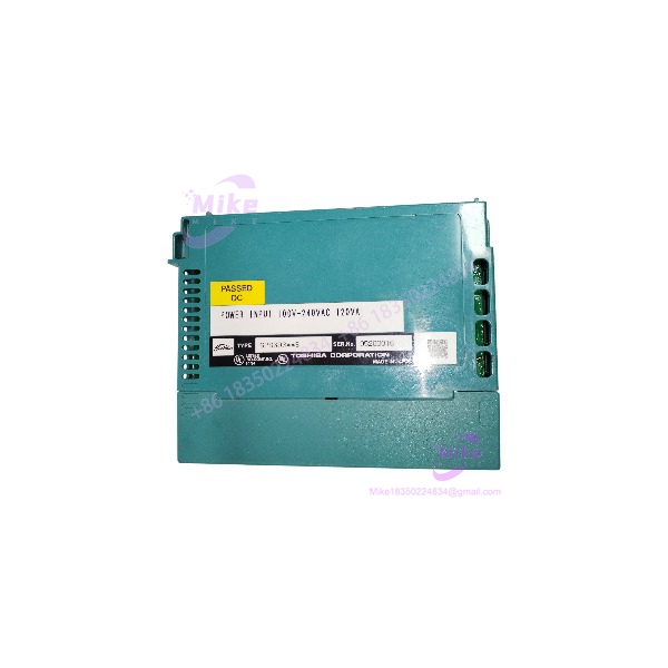
Toshiba GPS693 | V-Series Integrated Controller Power
Dynamic Product Introduction
Field engineers know that when a main power supply fails inside an active industrial control rack, the entire process loop goes dark in an instant. Finding a drop-in power module that maintains precise voltage regulation under fluctuating line conditions is critical to protecting sensitive CPU logic from brownouts and transient faults. The Toshiba GPS693 (also referenced under the PS693 architecture) serves as the core power distribution engine for Toshiba V-Series integrated controllers and type1/type2 light DCS setups.
Engineered to convert a universal 100–240 VAC input into stable multi-rail DC outputs, the GPS693 delivers high-amperage 5 VDC power to the backplane to drive local processing modules without thermal breakdown. (Honestly, keeping local rack logic powered cleanly prevents erratic I/O communication dropouts that can take hours to troubleshoot in the field.) Built with heavy-duty industrial filtering and integrated overcurrent protection, the GPS693 ensures your process control hardware runs smoothly—though long-term reliability strictly depends on maintaining proper cabinet thermal management.
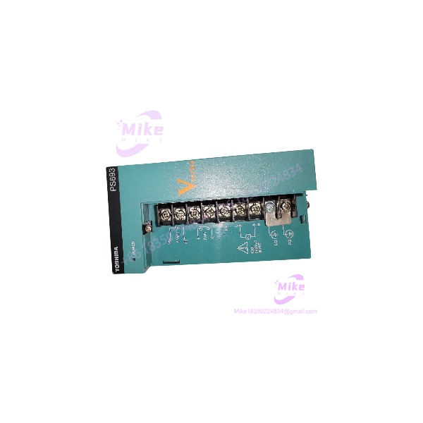
PS693
Key Technical Specifications
- Manufacturer & System Series: Toshiba V-Series / Integrated Controller Model 2000
- Nominal Input Voltage: 100 V to 240 V AC (120 VA rating)
- Permissible Input Voltage Range: 85 V to 264 V AC (47 Hz to 63 Hz frequency range)
- Primary Logic Output (5V Rail): 5.0 V DC @ 7.0 A max
- Auxiliary Logic Output (3.3V Rail): 3.3 V DC @ 1.0 A max
- Field/Loop Auxiliary Output (24V Rail): 24 V DC (±10%) @ 0.8 A max
- Inrush Current Limitation: Integrated soft-start thermistor protection
- Status Diagnostics: LED indicators for Line Power OK and Output Voltage OK status
- Enclosure Rating & Mounting: Panel-mountable rack slot module with backplane edge connector
- Operating Ambient Temperature: 0°C to +55°C (32°F to 131°F) continuous operational range
- Weight: Approximately 560 grams (1.23 lbs)
Global Sourcing & Live-Test SOP (Transparency Core)
Procuring secondary-market or surplus power supply hardware demands strict electrical verification before installation into a production control panel. Every Toshiba GPS693 unit passing through our distribution network undergoes a five-stage bench inspection protocol:
- Inbound Verification: Serial numbers, batch codes, and hardware revision letters (e.g., Rev C) are logged and verified against Toshiba factory records. We perform visual inspections of the terminal blocks, check heat sink fins for dust buildup, and test internal electrolytic capacitors for ESR degradation or venting.
- Live Simulation: The GPS693 power supply is installed onto an authentic V-Series rack backplane powered by an adjustable AC line transformer (Variac) to test operation across the entire 85–264 VAC input range.
- Diagnostics: Electronic dummy loads are applied simultaneously across all output rails (5.0V, 3.3V, and 24V). Using a Fluke 87V digital multimeter and an oscilloscope, we confirm that voltage regulation stays within ±2% and peak-to-peak AC ripple/noise remains under strict factory millivolt tolerances under full 7A load.
- Burn-In Testing: The module undergoes a continuous 12-hour full-load thermal soak test inside a heated test chamber while monitoring transformer housing temperatures via thermal imaging.
- Final Prep: Baseline electrical test reports are attached to the unit, terminal covers are secured, and the GPS693 is sealed in conductive anti-static moisture-barrier packaging.
The Field Engineer’s Pitfall Guide
❗ Overloading the 5V Backplane Amperage Limit:While the GPS693 provides a robust 7.0A output on the 5 VDC rail, accumulating high-density expansion I/O cards or high-draw communication modules on a single rack slot run can exceed this budget. Exceeding the 7A threshold causes the internal switching power supply to trip into foldback current limiting, which drops the backplane voltage and causes continuous, unpredictable CPU reset loops.
❗ Neglecting AC Input Neutral Grounding Integrity: Connecting the AC input terminals of the GPS693 without a solid, low-impedance protective earth (PE) ground connection compromises internal surge suppression. In field deployments, floating ground connections allow high-voltage line transients and electromagnetic interference (EMI) to pass directly into the 5V logic bus, leading to corrupted data transfers across the backplane.
❗ Hot-Swapping Under Live AC Power: Never pull or insert the GPS693 module from the backplane rack while primary AC power is applied. Swapping the power supply under load can cause severe arcing across the gold-plated backplane connector pins, damaging the backplane trace headers and corrupting neighboring CPU or memory cards.
Intent-Driven FAQ
Q: Are the Toshiba GPS693 and PS693 model designations interchangeable? Yes. The designation PS693 refers to the general power supply module type within the V-Series architecture, while GPS693 (often listed as GPS693S) is the detailed part number stamped on the unit label. They are functionally and physically identical drop-in replacements.
Q: Can I use the 24V DC output on the GPS693 to power external high-draw field actuators? No. The integrated 24 VDC output is rated for a maximum current draw of 0.8 A. It is designed primarily to power internal sensor loops, dry contact inputs, or local status lamps. Attempting to power heavy external solenoids, relays, or motor starters from this rail will trip the power supply’s internal overload protection.
Q: What indicates an internal power supply failure on the front panel of the GPS693? The front panel features status LEDs. If the primary input power is applied within the 85–264 VAC window but the Output OK LED remains unlit, the module has tripped an internal fuse or experienced a thermal breakdown on its secondary output stage.
Q: Does the GPS693 require manual voltage selection switches for 120V vs 240V AC operation? No. The GPS693 features an active wide-range switching front end that automatically accepts input voltages anywhere between 85 V AC and 264 V AC (47–63 Hz) without requiring manual jumper adjustments or voltage selection switches.
Q: What should I check if a newly installed GPS693 causes the V-Series CPU to show a fault LED? First, measure the DC output voltages directly at the backplane test points to confirm the 5.0 VDC rail is delivering power under load. If the voltage is low, calculate the total power consumption of all installed rack modules to ensure you haven’t exceeded the 7.0A backplane rating. Also, verify that the module is fully seated into the rack backplane slots.





