

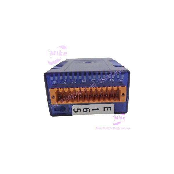
Description
Saia Burgess PCD3.A465 | Digital Output Module Key Spec Data
Architect’s Product Breakdown
The Saia Burgess PCD3.A465 operates as a reliable plug-in digital output card within modular programmable logic controller architectures, bridging internal controller logic with field actuators. In dense automation cabinets where panel space efficiency is critical, managing multi-channel switching without excessive thermal buildup is essential for long-term system reliability. This output module model delivers 16 independent transistor switching paths equipped with built-in short-circuit protection and local status LED indicators for rapid troubleshooting.
Deploying this expansion module model requires careful consideration of power distribution and total current draw across the backplane terminals. When upgrading or replacing hardware during a scheduled maintenance window, engineers must verify that external power feeds match the 10 to 32 VDC operational threshold. Failing to account for inductive kickback from unsuppressed inductive loads like solenoids or small DC contactors can quickly degrade internal transistor junctions and cause premature channel failure.
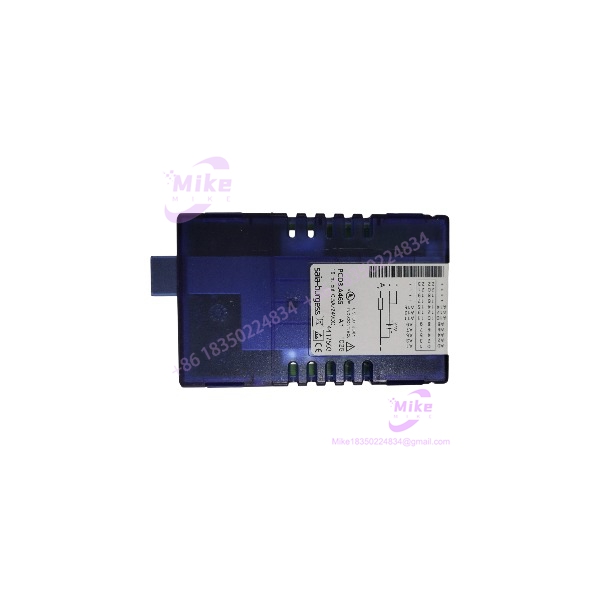
PCD3.A465
Key Technical Specifications
- Manufacturer: Saia Burgess Controls (Honeywell)
- Product Category: Digital Output Module
- Part Number / Catalog No.: PCD3.A465
- Number of Outputs: 16 transistor outputs (non-isolated common structure)
- Operating Voltage Range: 10 to 32 VDC
- Maximum Output Current: 0.5 A per channel (max 4 A total per module with external fusing)
- Output Voltage Drop: \le 0.3 V at 0.5 A
- Output Delay: Typically 50\,\mus, max 100\,\mus (resistive load)
- Termination Type: Removable plug-in spring terminals
- Operating Temperature Range: 0°C to +55°C
- Weight: Approximately 80 g
Field Engineer’s Pitfall Guide (Unique Value)
- Omitting External Fast-Blow Fuses: While the module features internal short-circuit protection, always install an external fast-blow fuse (maximum 4 A) on the supply rail to prevent catastrophic wiring damage during a severe field short.
- Hot-Swapping Under Power: Never plug or unplug this output module while the backplane and external +24 VDC supply are energized. Doing so can arc backplane pins and corrupt neighboring I/O communications.
- Ignoring Inductive Load Suppression: Failing to install flywheel diodes across DC inductive loads (such as heavy-duty relays or solenoids) will generate high-voltage voltage spikes that break down solid-state transistor switches over time.
QA & Testing SOP (Transparency)
- Visual & Origin Verification: Units undergo microscopic inspection to confirm clean PCB traces, secure housing latches, and authentic OEM markings.
- Live Test Bench Environment: Modules are inserted into a validation PCD3 test rack powered by regulated 24 VDC bench supplies to evaluate bus communication integrity.
- Load & Switching Validation: Technicians execute automated multi-channel switching cycles under simulated resistive and inductive loads to verify channel performance and LED status synchronization.
- Anti-Static Packaging: Post-testing units are wrapped in static-dissipative shielding material and packed with protective cushioning foam to prevent transit damage.
Technical FAQ
Can I hot-swap the PCD3.A465 module while the PLC rack is powered?No. I/O modules and terminal blocks must only be inserted or removed when both the PCD controller rack and the external power supplies are completely disconnected.
Are the 16 transistor outputs electrically isolated from one another?No. The individual circuits share an internal electrical connection and common ground path structure across the module base.
What causes the channel status LED to flash or fail to illuminate when commanded? A non-illuminated LED under an active software command typically points to an tripped output due to an external short circuit, an open load condition, or a missing external supply voltage on the terminal block.
What is the standard warranty status for surplus inventory units? Verified surplus or factory-sealed modules typically carry a 12-month operational warranty covering material and manufacturing defects under standard industrial environments.





