

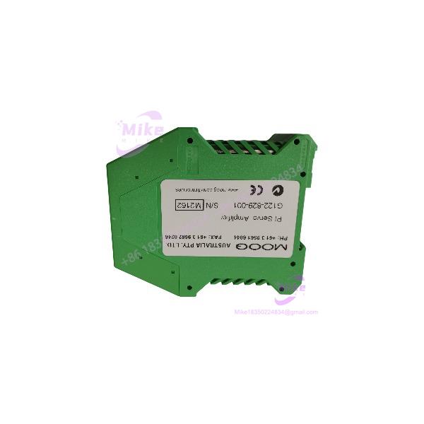
Description
MOOG G122-829-001 | DIN Rail P-I Servo Amplifier
Dynamic Product Introduction
The MOOG G122-829-001 is a purpose-built analog servo amplifier for machines where a PLC or controller needs to drive an electrohydraulic servo or proportional valve through a controlled closed loop. Rather than functioning as a generic analog output card, it combines command summing, proportional gain, integral control, feedback conditioning, dither, valve-drive control, and monitoring functions in one DIN-rail module.
Moog describes the G122-829-001 as a general-purpose, user-configurable P-I servo amplifier. Internal selector switches allow proportional control, integral control, or combined P + I operation. Front-panel potentiometers and test points are provided for commissioning and troubleshooting, while the amplifier accepts three analog inputs: two single-ended inputs and one differential input.
This model is especially important when maintaining older Moog-controlled hydraulic systems because Moog identifies G122-829-001 as the functional replacement for G122-824-002. The replacement is not electrically identical at the terminal level, however. Moog explicitly notes the different pinout and improved high-gain performance. That means the migration has to include a wiring review rather than simply moving the wires terminal-for-terminal.
The amplifier’s signal flexibility is substantial. Input 2 and the feedback input can be configured for 4–20 mA or ±10 V, while the output can be configured for voltage, current, or 4–20 mA. This makes the G122-829-001 suitable for a range of command and feedback architectures without requiring a separate signal-conditioning module.
G122-829-001
Key Technical Specifications
- Manufacturer: MOOG
- Part Number: G122-829-001
- Product Type: P-I servo amplifier
- Application: Closed-loop electrohydraulic servo/proportional valve control
- Control: P, I, or P + I
- Supply Voltage: 24 VDC nominal
- Supply Range: 22–28 VDC
- Maximum Supply Current: 200 mA
- Typical Supply Current: 75 mA at 24 V with no valve load
- Input 1: Single-ended, scalable; up to 95 V maximum with applicable switch configuration
- Input 2: 4–20 mA or ±10 V, switch selectable
- Input 3: ±10 V through configurable plug-in resistor
- Feedback Input: Differential 4–20 mA or ±10 V
- Feedback Input Maximum: ±15 V
- Feedback Gain: 1–10
- Transducer Excitation: +10 VDC at 10 mA maximum
- Proportional Gain: 1–20 with standard configuration
- Integrator Gain: 1–45 per second
- Enable Input: 17–32 VDC, approximately 8 mA
- Output Modes: Voltage, current, or 4–20 mA
- Voltage Output: ±10 V, minimum 200 Ω load
- Current Output: Selectable ±5, ±10, ±20, ±30, or ±50 mA; up to ±100 mA
- 4–20 mA Output: Maximum 500 Ω load
- Valve Supply: Terminal 23, 300 mA maximum
- In-Position Output: ±10% of valve drive; 20 mA / 40 V maximum
- Dither: 200 Hz fixed frequency, ±10% valve drive
- Mounting: DIN rail
- Protection: IP20
- Dimensions: 100 W × 108 H × 45 D mm
- Weight: 180 g
- Operating Temperature: 0 to +40°C
- Recommended Supply Protection: M205, 250 mA T slow-blow fuse
The detailed specifications above are based on Moog’s G122-829 application documentation and current G122-829A technical data.
One configuration detail deserves particular attention: tard documentation identifies R34 as a plug-in resistor associated with Input 2 scaling, while other functions such as feedback derivative and proportional-gain range also depend on plug-in resistor configuration. Therefore, the physical module alone does not tell the entire story of how a particular spare will behave.
Global Sourcing & Live-Test SOP
1. Inbound identification
Confirm the physical unit is marked:
- MOOG
- Correct hardware/revision information
- Intact terminal blocks
- Intact front-panel adjustment controls
- No corrosion or evidence of liquid contamination
- No cracked DIN housing
- No signs of unauthorized board modification
Keep the complete part number in the procurement record. Do not shorten it to “.”
2. Configuration capture
Before powering a used spare, document:
- Internal switch positions
- P/I selection
- Feedback input configuration
- Input 2 configuration
- Output configuration
- Dither setting
- Integrator limit
- Plug-in resistor values
- P gain
- I gain
- Feedback gain
- Feedback zero
- Input scaling
This step is particularly important for a replacement of an existing G122-824-002.
3. Power-supply test
Apply a controlled 24 VDC source and confirm the supply remains within the documented 22–28 V range.
Moog specifies a recommended 250 mA slow-blow supply fuse. The actual valve-load requirement must be considered separately because the valve supply can draw additional current.
4. Analog simulation
A proper bench test should simulate the intended control loop rather than merely energizing the amplifier.
Depending on the application, test:
- ±10 V command
- 4–20 mA command
- ±10 V feedback
- 4–20 mA feedback
- Enable input
- Transducer excitation
- Valve-drive output
- In-position output
Use calibrated voltage/current measurement equipment to confirm the amplifier follows the expected scaling.
5. Output-stage verification
Check the actual selected output configuration.
The can provide:
- ±10 V voltage output
- Selectable current output
- 4–20 mA output
The selected output must match the servo/proportional valve interface. A current-controlled valve must not be commissioned using assumptions based on a voltage-output configuration.
6. Closed-loop commissioning
Where practical, connect the actual feedback transducer and valve under controlled conditions.
Verify:
- Correct command direction
- Feedback polarity
- Zero position
- Gain
- Integral action
- Dither
- Enable behavior
- Valve response
- In-position indication
Do not tune a hydraulic loop aggressively on the first power-up. Start with conservative gain settings and verify feedback polarity before increasing loop gain.
7. 24-hour heat run
For a critical spare, operate the amplifier under representative electrical conditions for 24 hours. Monitor supply current, output stability, front-panel LEDs, enclosure temperature, and signal drift.
This is particularly worthwhile for used analog amplifiers because intermittent adjustment or thermal problems can be difficult to identify during a five-minute bench check.
Field Engineer’s Pitfall Guide
1. is a replacement for G122-824-002, but it is not a wire-for-wire replacement.
This is the biggest procurement trap. Moog explicitly idethe as the functional replacement for the G122-824-002 with a different pinout.
If the old amplifier is being replaced during a shutdown, document every terminal before removal and compare the old and new wiring diagrams. A terminal-number assumption can put the command, feedback, or valve circuit on the wrong connection.





