
Description
Kongsberg RDIOR400 | Remote Digital Input/Output Relay Module
Dynamic Product Introduction
Chief electronics officers and marine automation engineers managing DP-2/DP-3 offshore vessels, container ships, and LNG carriers understand how critical localized I/O signal acquisition is for central machinery control. When a remote digital I/O relay card handling main engine safety alarms, valve feedback, or thruster status contacts suffers relay contact welded conditions, channel isolation loss, or fieldbus transceiver failure, replacing the module quickly without disrupting adjacent I/O loops is an essential operational priority.
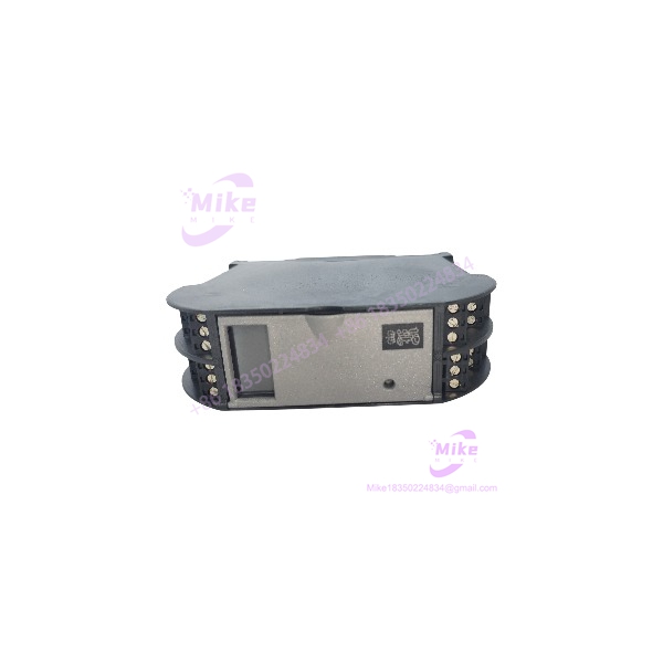
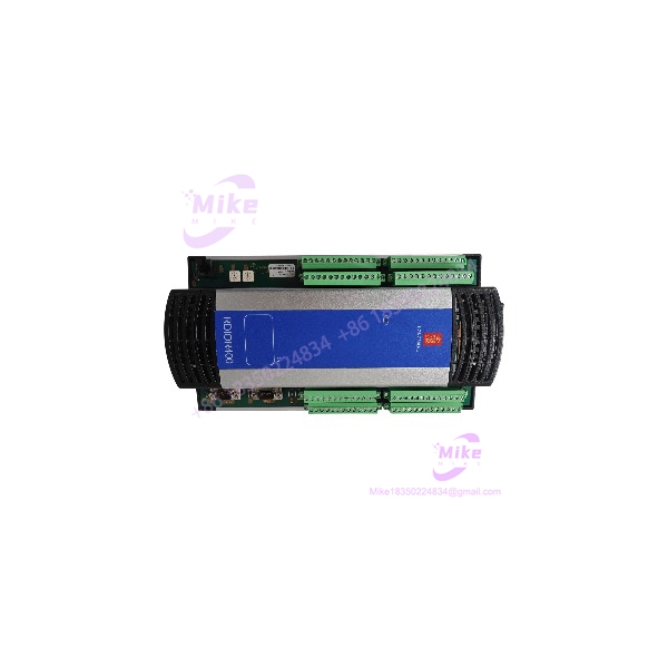
The Kongsberg Maritime RDIOR400 is a high-density, marine-grade Remote Digital Input/Output Relay Module designed for integration into K-Chief and K-Pos automation suites. Built to operate in harsh machinery space environments, the RDIOR400 collects discrete contact signals (such as limit switches, level switches, and breaker statuses) and executes dry-contact relay outputs for valve actuation, alarm annunciators, and motor control circuits. Interfaced via redundant marine fieldbus networks, the RDIOR400 ensures zero-single-point-of-failure communication back to central RCU processing units.
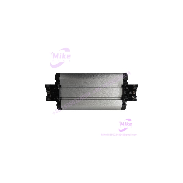
RDIOR400
Key Technical Specifications
- Operating Supply Voltage: Dual Redundant 24 V DC (18 to 32 V DC operational range)
- Digital Input Channels: High-density optocoupler-isolated 24 V DC digital inputs (voltage-free contact monitoring)
- Relay Output Channels: Electromechanical relay output channels (changeover / dry-contact configuration)
- Relay Contact Rating: Up to 250 V AC / 30 V DC (2 A to 5 A per contact, depending on inductive load class)
- Fieldbus Network Ports: Dual redundant CANbus / RNet marine fieldbus communication interfaces
- Galvanic Isolation: Optical and transformer isolation across power inputs, fieldbus lines, and I/O channels
- Operating Temperature Range: -15 °C to +70 °C harsh marine ambient rating
- Marine Type Approval: Certified by major classification societies (DNV, ABS, Lloyd’s Register, Bureau Veritas, RINA)
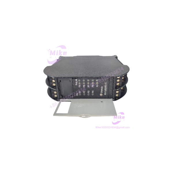
- Status Diagnostics: Front panel LED indicators for power feeds A/B, fieldbus communications, and individual channel I/O status
Global Sourcing & Live-Test SOP (Transparency Core)
Sourcing surplus or replacement marine remote I/O modules requires rigorous channel-by-channel signal and fieldbus verification under simulated vessel load conditions.
Inbound Verification & Traceability
- Paperwork Audit: Verification of physical serial numbers, revision plates, and software/hardware build codes against Kongsberg Maritime manufacturing archives.
- Physical Inspection: Detailed check of housing seals, conformal coating integrity across internal PCBs, terminal block tension screws, and relay contact surfaces for signs of arcing or thermal stress.
Live Bench Simulation & Diagnostics
- Redundant Power Rail Test: Module is powered using dual independent 24 V DC marine power supplies, cycling feeds A and B to verify seamless auto-failover without dropping active relay channels.
- Digital Input Optical Channel Sweep: Applying 24 V DC discrete inputs to all channels while observing status LED responsiveness and checking isolation integrity via high-impedance meters.
- Relay Output Load & Contact Resistance Check: Cycling all output relays under maximum rated current load while measuring contact resistance (must read < 50 mΩ) to rule out high-resistance contact pitting.
- Redundant Fieldbus Handshake: Interfaced with a test K-Chief/K-Pos controller over primary and secondary fieldbus channels to confirm node discovery, I/O mapping, and packet integrity.
- 24-Hour Thermal Burn-In: Module undergoes a 24-hour thermal chamber stress run under continuous relay cycling to ensure zero thermal drift or coil degradation.
Final Prep
- Node Address & Dip Switch Reset: Setting rotary/DIP node address switches to factory default or customer-specified node IDs.
- ESD & Marine Packaging: Unit is sealed in heavy-duty anti-static barrier film with moisture-absorbing desiccant packs before double-boxed shipping.
Machinery Actuation & Electrical Safety Hazard
Replacing an active RDIOR400 module must never be performed while connected equipment (e.g., fuel cut-off valves, fire dampeners, or high-voltage switchgear breakers) is live and operational. Swapping relay cards can trip output contacts during initial power-up, causing unexpected machinery state changes. Always isolate field contact power and place actuators in manual bypass mode prior to hardware replacement.
The Field Engineer’s Pitfall Guide
- ❗ Matching Node Address DIP Switches: The RDIOR400 identifies itself on the RNet/CANbus fieldbus network via hardware rotary or DIP switches located on the PCB/housing. Installing a replacement unit without transferring the exact hardware address set from the old card will prevent the master RCU processor from establishing I/O communication.
- ❗ Inductive Load Suppression: When driving inductive loads (such as solenoid valves, heavy contactor coils, or electromechanical brakes) directly from the RDIOR400 relay contacts, install external RC snubbers (for AC loads) or freewheeling flyback diodes (for DC loads) across the coil. Unsuppressed inductive back-EMF spikes will weld or severely pit the internal relay contacts.
- ❗ Floating DC Bus Grounding Limits: Auxiliary 24 V DC power networks supplying the module must remain strictly floating relative to the vessel’s steel hull. Introductions of ground faults via field contact wiring will trigger “24V Earth Fault” alarms on the main K-Chief engine control room console.
Intent-Driven FAQ
Will swapping out a damaged RDIOR400 require re-programming the central K-Chief system?
No. The RDIOR400 is an I/O slave card. As long as the replacement unit’s hardware node address (DIP switches/rotary dials) matches the defective module, the central master controller (RCU) will automatically map the digital inputs and relay outputs upon power-up.
What are the primary symptoms of a failing RDIOR400 module?
Common indicators include intermittent channel loss on the K-Chief operator screen (“I/O Module Fault” or “Node Offline” alarms), failure of relay output channels to energize despite command indication on the software console, or status LEDs failing to illuminate when field contacts close.
Can the RDIOR400 be installed directly inside engine room cabinets?
Yes. The RDIOR400 is marine type-approved for installation in ambient temperatures up to +70 °C and features conformal coating on all internal circuit boards to resist moisture, vibration, and salt-air corrosion typical of engine control rooms.
What do the LED indicators on the front panel display?
- POWER A / B: Green LEDs indicate active redundant 24 V DC power supplies.
- COMM / NET: Flickering green/yellow indicates active fieldbus communication with the master processor.
- I/O STATUS: Individual LEDs indicate the real-time ON/OFF state of each digital input and relay output channel.
What warranty coverage is provided on replacement hardware?
All verified Kongsberg Maritime RDIOR400 modules include a standard 12-month full-replacement warranty covering internal logic circuitry, fieldbus transceivers, digital input optocouplers, and relay output contact assemblies.