

Description
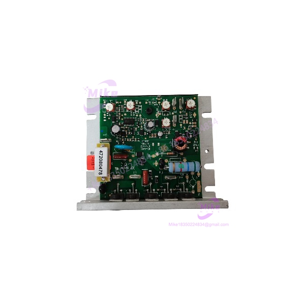
KB Electronics KBLC-120 | DC Motor Speed Control
Product Introduction
A legacy DC motor system can become difficult to maintain when its original speed controller is no longer readily available. The KB Electronics KBLC-120 is a compact DC motor speed control used in applications where a compatible DC motor requires adjustable armature voltage rather than a modern AC variable-frequency drive.
The KBLC-120 is designed for a nominal 120 VAC line supply and DC motor voltages in the 90–130 VDC range. Its current and horsepower capability depend on the installation: the OEM manual specifies 6 A average DC load without an auxiliary heatsink and up to 12 A with the specified heatsink arrangement. This distinction matters when sourcing a replacement, because the controller board alone should not be assumed to provide the maximum listed motor rating.
For maintenance teams, the key procurement issue is configuration matching. Verify the controller’s full model designation, installed horsepower resistor, heatsink arrangement, motor nameplate, and control wiring before installation. A visually similar DC drive is not automatically an electrically equivalent replacement.
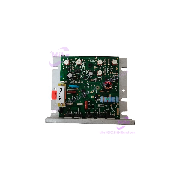
KBLC-120
Key Technical Specifications
- Manufacturer: KB Electronics
- Model: KBLC-120
- Controller Category: DC motor speed control
- Nominal AC Line Voltage: 120 VAC
- AC Line Frequency: 50/60 Hz
- DC Motor Voltage Range: 90–130 VDC
- Average DC Load Current: 6 A without auxiliary heatsink
- Average DC Load Current With Auxiliary Heatsink: 12 A
- Maximum Motor Rating Without Auxiliary Heatsink: 1/2 HP
- Maximum Motor Rating With Auxiliary Heatsink: 1 HP
- Supported Motor Types: PM and shunt-wound DC motors
- Speed Adjustment: Main speed potentiometer with minimum and maximum speed trimpots
- Acceleration Adjustment: Adjustable acceleration-start function
- Current Limiting: Adjustable current-limit circuitry
- Load Regulation: IR compensation adjustment
- Analog Reference: Isolated 0–9 VDC reference input supported
- Motor Matching: Plug-in horsepower resistor required
- Thermal Installation Limit: OEM manual specifies a maximum ambient temperature of 50°C at full rating
- Mounting: Flat surface or suitable enclosure with adequate heat dissipation
Important: These are KBLC-120 family specifications from the available OEM manual. Confirm the exact board revision, installed options, and nameplate before applying them to a specific surplus unit.
Global Sourcing & Live-Test SOP
For a used or surplus KBLC-120, a visual inspection alone is not sufficient. The drive should be evaluated as a power-electronic component with configuration-dependent motor ratings.
1. Inbound Verification
- Photograph the complete nameplate and all board markings.
- Confirm the model is , not KBLC-240 or another KB Electronics controller.
- Record any suffix, revision, or additional part number, such as 9109A or 9109H, where present.
- Inspect the PCB, terminals, adjustment components, and power devices for physical damage.
- Check for heat discoloration, cracked solder joints, corrosion, contamination, or previous repair work.
- Confirm whether the auxiliary heatsink, terminal board, fuse accessories, or other options are included.
- Inspect the horsepower resistor and record its value or part number where identifiable.
2. Electrical and Visual Inspection
- Verify that the intended supply voltage matches the controller’s actual rating.
- Inspect line and motor terminals for damage or signs of overheating.
- Check fuse holders and installed fuses against the applicable documentation.
- Inspect the board for damaged components, loose hardware, and contamination.
- Confirm that the planned enclosure provides adequate ventilation and heat dissipation.
- Do not energize a unit with uncertain wiring, damaged insulation, or unresolved component damage.
3. Controlled Power-Up and Functional Test
Testing should be performed by qualified personnel using suitable electrical safety procedures and an appropriately protected test setup.
- Confirm the correct motor type and rating before testing.
- Verify that the required plug-in horsepower resistor is installed.
- Apply the correct AC input under controlled conditions.
- Check startup behavior and speed-control response using a compatible test motor.
- Verify minimum and maximum speed adjustments.
- Check acceleration behavior and current-limit response using an appropriate test procedure.
- Confirm stable operation through the intended operating range.
- Record abnormal noise, odor, excessive heating, unstable speed, or unexpected current draw.
4. Analog Reference and Control Checks
Where the application uses an external analog speed command:
- Verify the controller’s reference-input configuration.
- Confirm that the 0–9 VDC reference is isolated as required by the OEM instructions.
- Check speed response to the reference signal.
- Inspect signal wiring for routing alongside AC line or motor conductors.
- Verify that the controller responds consistently across the required command range.
Safety note: The OEM manual warns that the controller circuitry is not isolated from the AC line. Do not treat its control terminals as inherently safe or SELV-rated. Follow the manual’s grounding, isolation, wiring, and enclosure requirements.
5. Extended Run and Final Documentation
For a unit represented as tested, perform an application-appropriate extended run with a compatible motor and load.
Record:
- Test date and duration
- Applied AC line voltage
- Motor voltage, current, and nameplate rating
- Installed horsepower resistor
- Heatsink configuration
- Speed-control response
- Current-limit and acceleration behavior
- Observed faults or abnormal heating
Use ESD-safe packaging for the electronic assembly. Protect terminals and adjustment components from impact during shipment. Do not claim a successful load test unless the test was actually completed and documented.
Field Engineer’s Pitfall Guide
❗ 1. Heatsink configuration changes the usable rating
The ‘s documented current and horsepower ratings differ depending on whether the specified auxiliary heatsink is installed. Do not assume a bare controller board supports the maximum heatsink-assisted rating. Confirm the actual assembly and its thermal installation.
❗ 2. The horsepower resistor is not an optional detail
The OEM manual specifies a plug-in horsepower resistor matched to motor horsepower and voltage. An incorrect or missing resistor can compromise the intended setup and current-limit/IR compensation behavior. Verify the resistor before commissioning.
❗ 3. Do not assume the control circuitry is isolated from line voltage
The is not an isolated low-voltage controller. Its OEM manual warns that the circuitry is not isolated from the AC line. External reference wiring, grounding, fusing, and maintenance procedures must account for this. Never use the inhibit or enable circuit as a safety disconnect.
Intent-Driven FAQ
What is the KB Electronics used for?
The is a variable-speed DC motor controller used to regulate compatible PM or shunt-wound DC motors. It is not a PLC, servo drive, or AC variable-frequency drive.
What input voltage does the require?
The OEM manual specifies a nominal 120 VAC line supply at 50/60 Hz. Confirm the unit’s nameplate and wiring documentation before connecting power.
What is the output voltage of the ?
The documented motor voltage range is 90–130 VDC. Actual motor compatibility depends on the motor nameplate, controller setup, and application requirements.
What is the current rating of the ?
The OEM manual lists 6 A average DC load without an auxiliary heatsink and 12 A with the specified auxiliary heatsink. Verify the physical configuration before selecting the controller for a replacement application.
Does the support an external speed reference?
Yes. The OEM manual describes operation from an isolated 0–9 VDC analog reference in place of the main speed potentiometer. Wiring and isolation requirements must be followed.
Is the a direct replacement for every listing?
Not necessarily. Confirm the full model and suffix, board revision, horsepower resistor, heatsink arrangement, motor rating, and control wiring. A matching base model number alone does not confirm that all installed options are equivalent.
What should I verify before buying a used ?
Request clear photographs of the model markings, PCB, terminals, and included accessories. Confirm the unit’s condition, heatsink configuration, resistor installation, and whether it has been functionally tested. Do not assume that a used or surplus listing includes a warranty or tested operating condition unless the seller explicitly documents it.
Bottom Line for Buyers
The KB Electronics is a legacy DC motor speed controller intended for compatible 90–130 VDC motor applications using a nominal 120 VAC line supply. Its practical replacement suitability depends on the motor rating, horsepower resistor, heatsink configuration, and control wiring—not simply the model designation.
When sourcing this controller, request the complete nameplate and board photos, confirm included accessories, and obtain a clear statement of test status. Those checks help distinguish a usable replacement assembly from a bare or mismatched drive board.





