


Description
Foxboro FBM242 RH916TA | 15–60 VDC 2A Output Module
Product Introduction
RH916TA is the module. That distinction matters.
For the Foxboro FBM242, Schneider’s PSS documentation identifies RH916TA as the current module part number and explicitly states that it supersedes P0916TA. The FBM242 is a 16-channel externally sourced discrete output interface designed for switching industrial field loads from the I/A Series control system.
The output architecture is centered on externally supplied field power. Depending on the selected termination assembly, the FBM242 system can handle direct 15–60 VDC switching or use relay-based interfaces for higher-voltage AC/DC loads. This is why the module and TA should be treated as two separate procurement items when replacing installed hardware.
The FBM242 RH916TA also supports discrete I/O and Ladder Logic execution, configurable fail-safe behavior, sustained or momentary outputs, and redundant 2 Mbps Fieldbus communication.
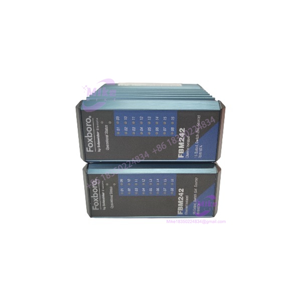
FBM242 RH916TA
Key Technical Specifications
- Module: FBM242
- Module part number: RH916TA
- Previous part number: P0916TA
- I/O type: Discrete output
- Number of channels: 16
- Output architecture: Externally sourced
- Direct DC output range: 15–60 VDC
- Maximum direct DC output: 2 A per channel
- Power supply: 24 VDC, +5% / -10%
- Maximum module consumption: 3 W at 24 VDC
- Maximum heat dissipation: 6.5 W under the specified loaded condition
- Fieldbus: Redundant 2 Mbps module Fieldbus
- Channel isolation: Provided by the for the direct solid-state output configuration
- Application processing: Discrete I/O or Ladder Logic
- Fail-safe configuration: Supported
- Fail-safe fallback: Supported
- Output modes: Sustained or momentary
- Operating temperature: -20 to +70°C (-4 to +158°F)
- Relative humidity: 5–95%, noncondensing
- Environmental class: G3 harsh industrial environment
- Module weight: Approximately 284 g
- Module dimensions: 102 mm H × 45 mm W × 104 mm D
- Height including mounting lugs: 114 mm
The 15–60 VDC / 2 A specification belongs to the externally sourced solid-state output configuration. It should not be applied indiscriminately to every termination arrangement.
RH916TA Output Architecture
The provides sixteen independently controlled discrete outputs.
For the direct external-source configuration, the field circuit supplies the load power while the provides the switching function. Schneider documents a maximum of 2 A per channel at 15–60 VDC for the protected and unprotected solid-state termination configurations.
This architecture is suitable for applications such as:
- DC solenoid valves
- Interposing relays
- Contactor coils
- Motor starter interfaces
- Alarm circuits
- Actuator control
- Other discrete DC loads
The field load still needs to be evaluated for steady-state current, inrush current, inductive energy, suppression requirements, and field-voltage drop.
Termination Assembly Compatibility
This is the part most likely to cause a procurement mistake.
RH916TA is the module. The termination assemblies have different part numbers.
Schneider’s documentation lists, among others:
- RH916JY — protected/fused 15–60 VDC external-source outputs, 2 A maximum
- RH917XX — unprotected 15–60 VDC external-source outputs, 2 A maximum
- RH917HX — protected outputs with power distribution; 15–60 VDC, 2 A maximum, with 12 A maximum for each group of eight channels simultaneously
- RH923LH — individually protected redundant-power configuration, 15–60 VDC, 2 A maximum
- RH916YY — relay termination, externally sourced
- RH916YZ — relay termination with power distribution
The relay termination configurations can provide substantially different field ratings, including less than 30 VDC at 5 A, 125 VDC at specified resistive/inductive current levels, and up to 250 VAC at 5 A, depending on the exact TA and load category.
So an order reading only identifies the module, not necessarily the complete field termination package.
Physical and Installation Details
mounts on a Foxboro modular baseplate.
The baseplate can be installed:
- Horizontally or vertically on DIN rail
- Horizontally in a 19-inch rack using the appropriate mounting kit
The module is approximately 102 mm high × 45 mm wide × 104 mm deep, increasing to approximately 114 mm in height when mounting lugs are included. The documented module mass is approximately 284 g.
Termination assemblies mount separately on DIN rail.
termination cables can be up to 30 m (98 ft) and use polyurethane or LSZH cable construction. Type 4 and Type 4H cable configurations are documented for the module family, with a 37-pin male D-subminiature interface.
Fieldbus and Control Functions
The communicates with the Foxboro control system through a redundant 2 Mbps module Fieldbus.
At the application level, the module supports:
- Discrete I/O processing
- Ladder Logic
- Configurable fail-safe behavior
- Fail-safe fallback
- Sustained outputs
- Momentary outputs
This means troubleshooting should not stop at “the Fieldbus is online.”
A healthy communication link proves that the control processor can communicate with the FBM. It does not automatically prove that the field supply, TA, output switching circuit, wiring, fuse, relay, or final load is healthy.
Global Sourcing & Live-Test SOP
For a used, surplus, or refurbished , the acceptance procedure should distinguish the module from its termination assembly.
1. Inbound Verification
- Confirm the label reads .
- Verify the module part number as .
- Check for the superseded P0916TA designation where applicable.
- Photograph serial number and hardware revision.
- Inspect the enclosure and baseplate connector.
- Check for corrosion, contamination, overheating, cracked plastic, or bent pins.
- Confirm the customer’s required TA separately.
2. Live Simulation
Use an approved Foxboro I/A Series test rack.
- Apply 24 VDC within the specified tolerance.
- Establish redundant Fieldbus communication.
- Exercise all 16 output channels individually.
- Use an appropriate external field supply.
- Measure output voltage under representative load.
- Measure load current with a calibrated Fluke multimeter or equivalent.
- Test representative inductive loads where applicable.
- Verify DCS output status and module diagnostics.





