


Description
FLOWSERVE F5-MEC-420 | PMV Valve Feedback Unit
Dynamic Product Introduction
A control valve can continue moving mechanically while the control system believes it is somewhere else. That mismatch is where process instability begins.
The FLOWSERVE F5-MEC-420 is a valve position feedback unit designed for PMV F5 series actuator and positioner installations. It combines mechanical switching feedback with an analog 4–20 mA transmitter, allowing the control system to monitor valve position continuously while also receiving discrete end-position signals.
Unlike a simple limit switch box, the F5-MEC-420 provides both confirmation and measurement. The two SPDT switches can be used for open/close indication, alarms, or interlocks, while the 4–20 mA output provides proportional valve position feedback to a PLC, DCS, or process controller.
In field maintenance, the difficult part is not mounting the feedback unit. The difficult part is maintaining correct mechanical alignment between actuator travel and transmitter output. A few degrees of misalignment can create false valve position readings, especially on modulating applications.
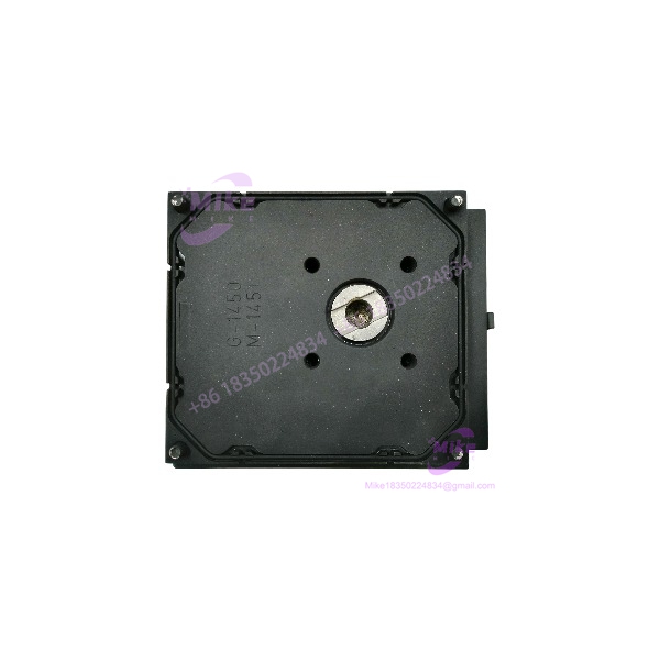
F5-MEC-420
Key Technical Specifications
- Model: F5-MEC-420
- Manufacturer: FLOWSERVE / PMV
- Product Family: F5 Feedback Unit
- Application: Valve actuator position feedback
- Feedback Type: Mechanical switches + analog transmitter
- Switch Configuration: 2 × SPDT switches
- Switch Rating: 6 A / 2.5 A at 250 VAC (application dependent)
- Analog Output: 4–20 mA position transmitter
- Maximum Transmitter Supply: 28 VDC
- Position Feedback: Continuous rotational position indication
- Mounting Application: PMV F5 series actuator/positioner assemblies
- Mechanical Adjustment: Cam-based switch positioning
- Electrical Connection: Depends on F5 enclosure variant
- Operating Environment: Industrial valve automation applications
- Available Variants: F5NU, F5IS, F5EX configurations depending on hazardous-area requirements
The suffix matters.
The F5-MEC-420 describes the feedback configuration:
- MEC = 2 × SPDT mechanical switches
- 420 = 4–20 mA transmitter feedback
Complete assemblies may include additional codes for enclosure type, hazardous-area certification, spindle configuration, and indicator options.
Global Sourcing & Live-Test SOP
For surplus FLOWSERVE F5-MEC-420 inventory, a continuity check alone is not enough.
A feedback unit may show correct switch operation while the transmitter output is inaccurate due to mechanical wear, calibration drift, or damaged internal components.
Inbound Verification
Each incoming F5- should receive:
- Exact model identification
- Serial number recording
- Nameplate inspection
- Housing condition check
- Cable entry inspection
- Mechanical shaft inspection
Verify:
- F5- marking
- Feedback type
- Hazardous-area certification marking if applicable
- Mechanical mounting condition
Do not confuse standard F5 feedback units with explosion-proof or intrinsically safe versions. The enclosure certification can affect replacement approval.
Live Simulation
A proper test should reproduce actuator movement.
Recommended procedure:
- Mount the feedback unit on a controlled actuator simulator.
- Supply the transmitter loop power.
- Rotate through full mechanical travel.
- Measure 4–20 mA output response.
- Activate both SPDT switches.
Verification points:
- Fully closed position
- Mid travel position
- Fully open position
Expected behavior:
- Approximately 4 mA at one calibrated endpoint
- Approximately 20 mA at the opposite endpoint
- Stable current output throughout travel
The switch cams should also be checked for repeatable actuation points.
Diagnostics
Recommended tools:
- Fluke multimeter with current measurement
- 24 VDC loop supply
- Continuity tester
- Mechanical angle reference tool
Diagnostic checks:
- Verify 4 mA zero position.
- Verify 20 mA full position.
- Confirm linear output change.
- Check switch contact resistance.
- Perform repeated travel cycles.
- Monitor output stability.
A common field issue is not electronic failure. It is incorrect mechanical calibration after installation.
Final Preparation
Before shipment:
- Record transmitter output range.
- Record switch operation results.
- Document mechanical condition.
- Protect shaft coupling components.
- Use ESD-safe and moisture-protected packaging.
For valve automation spares, traceability matters because incorrect feedback can create unsafe process conditions.
The Field Engineer’s Pitfall Guide
❗ Do not replace an F5- without checking actuator travel calibration.
The 4–20 mA signal depends on mechanical positioning. A replacement installed with incorrect cam adjustment may report 20% valve travel when the valve is actually closed. I have seen operators chase PLC scaling problems when the real issue was mechanical alignment.
❗ Do not ignore hazardous-area certification differences.
An F5IS or F5EX version may be required for classified areas. Replacing a certified feedback assembly with a standard enclosure can invalidate the installation approval.
❗ Do not assume the switch configuration is interchangeable.
The MEC version uses two mechanical SPDT switches. Other F5 configurations use NAMUR sensors or proximity switches. The PLC/DCS input design must match the actual feedback hardware.
Intent-Driven FAQ
What is the FLOWSERVE F5- used for?
The FLOWSERVE F5- is a valve position feedback unit used with PMV F5 series actuator and positioner systems. It provides both discrete switch feedback and continuous 4–20 mA position feedback.
Does the F5- replace a digital valve positioner?
No. The F5- is a feedback assembly. It provides position information but is not a complete valve controller.
What signal does the F5- output?
The unit provides a 4–20 mA analog position feedback signal through its transmitter section.
How many switches are included in the F5-?
The MEC configuration includes two SPDT mechanical switches for position indication or alarm functions.
Can I install an F5- on any actuator?
Not automatically. Confirm mechanical coupling, spindle configuration, enclosure type, and hazardous-area requirements before replacement.
Does the F5- require calibration after installation?
Yes. The transmitter output and switch points normally require mechanical adjustment to match actual valve travel.
How should a used F5- be tested before installation?
A proper test should include:
- Mechanical travel simulation
- 4–20 mA output verification
- Switch continuity testing
- Repeated position cycling
- Physical inspection
Procurement verdict: The FLOWSERVE F5- is a specialized valve feedback assembly used where reliable position indication is required for actuator monitoring and process control. Its value comes from combining mechanical limit switching and continuous 4–20 mA feedback in one F5-series package.
For replacement sourcing, verify the complete configuration: F5- code, actuator compatibility, switch type, transmitter output, enclosure certification, and mechanical calibration requirements. The part number identifies the hardware, but the valve application determines whether it is the correct replacement.





